"The woman is created for a man, not a man for a woman" - such a postulate ...


The design of gas fire extinguishing systems is a rather complex intellectual process, the result of which the workable system becomes reliably, and effectively protect the object from fire. This article discusses and analyzedproblems arising from the design of automaticgas fire extinguishing installations. Estimated maybedata data systems and their effectiveness, as well as relativesright possible options Optimal constructionautomatic systems Gas fire extinguishing. Analysisthese systems are made in full compliance withcP Rules 5.13130.2009 and other rulessNiP, NPB, GOST and Federal laws and ordersRF on automatic fire extinguishing installations.
Chief Engineer project LLC "ASPT SpecialAvtomatika"
V.P. Sokolov
To date, one of the most effective means of extinguishing fires, in the premises of the AUPT automatic fire extinguishing facilities in accordance with the requirements of the SP 5.13130.2009, the application "A" are the installations of automatic gas fire extinguishing. Type of automatic extinguishing installation, extinguishing method, view of fire extinguishing agents, type of equipment installation fire automation Determined by the organization-designer, depending on the technological, constructive and volume-planning features of protected buildings and premises, taking into account the requirements of this list (see paragraph. A.3.).
The use of systems where the fire extinguishing agent during fire automatically or remotely in manual start-up mode is supplied to the protected room is especially justified when protecting expensive equipment, archival materials or values. Automatic fire extinguishing installations allow you to eliminate the ignition of solid, liquid and gaseous substancesas well as electrical equipment under voltage. This extinguishing method may be volumetric - when creating a fire extinguishing concentration throughout the volume of the protected room or local - if the fire extinguishing concentration is created around the protected device (for example, a separate unit or unit technological equipment).
When choosing optimal option Management of automatic fire extinguishing installations and the choice of fire extinguishing agent is usually guided by the norms, technical requirements, features and functionality of protected objects. Gas fire extinguishes with the correct selection practically do not damage the protected object in it with equipment with any industrial and technical purpose, as well as the health of the staff working in the protected premises with a permanent stay. The unique gas ability to penetrate the cracks into the most inaccessible places and effectively affect the focus of ignition gained the widespread distribution in the use of gas extinguishing substances in automatic gas fire extinguishing installations in all areas of human activity.
That is why automatic gas fire extinguishing installations are used to protect: data processing centers (data center), server, telephone bonds, archives, libraries, museum stoves, banks' cash repositories, etc.
Consider the varieties of fire extinguishing substances most commonly used in automatic gas fire extinguishing systems:
Cladon 125 (C 2 F 5 H) The regulatory bulk fire extinguishing concentration of n-heptane GOST 25823 is 9.8% of the volume (corporate name HFC-125);
Claudone 227EA (C3F7H) The regulatory bulk fire extinguishing concentration of n-heptane GOST 25823 is equal to - 7.2% of the volume (branded name FM-200);
Claudone 318C (C 4 F 8) The regulatory bulk fire extinguishing concentration of n-heptane GOST 25823 is - 7.8% of the volume (corporate name HFC-318C);
Cladon FC-5-1-12 (CF 3 CF 2 C (O) CF (CF 3) 2) Regulatory volumetric concentration of n-heptane GOST 25823 is equal to - 4.2% of the volume (NOVEC 1230 proprietary name);
Carbon dioxide (CO 2) The regulatory volumetric fire extinguishing concentration of n-heptane GOST 25823 is - 34.9% of volume (can be used without constant stay of people in the protective room).
We will not analyze the properties of gases and their principles of influence on the fire in the fire focus. Our task will be the practical use of these gases in automatic gas fire extinguishing installations, the ideology of constructing these systems in the design process, the issues of calculating the mass of the gas to ensure the regulatory concentration in the amount of protected room and determine the diameters of the supply and distribution pipe pipes, as well as the calculation of the exhaust area of \u200b\u200bthe nozzle .
In gas fire extinguishing projects when filling in the drawing stamp, title sheets And in the explanatory note, we use the term automatic installation of gas fire extinguishing. In fact, this term is not entirely correct and correct will be the use of the term automated gas fire extinguishing.
Why is that! We look at the list of terms in the joint venture 5.13130.2009.
3.1 Automatic Fire Extinguishing Installation Start: Starting installation from its technical means without human participation.
3.2 Automatic installation Fire extinguishing (AUP): Installation of fire extinguishing, automatically triggered by exceeding the controlled factor (factors) of the fire of installed threshold values \u200b\u200bin the protected zone.
In the theory of automatic control and regulation there is a separation of terms Automatic control and automated control.
Automatic systems - This is a complex of software and technical means and devices working without human participation. The automatic system does not necessarily have a complex device complex, to manage engineering systems and technological processes. It can be one automatic device performing set functions According to a predetermined program without human participation.
Automated systems - This is a complex of devices that transform information into signals and transmitting these signals to the distance via the communication channel for measurement, alarm and management without human participation or with its participation of no more than one side of the transmission. Automated systems This is a combination of two automatic and manual control systems (remote) control systems.
Consider the composition of automatic and automated systems for controlling active fire protection:
Funds for obtaining information information collection devices.
Means for transmitting information lines (Channels) communication.
Means for receiving, processing information and issuing control signals of the lower level local receptions electrotechnical devicesdevices and control and control stations.
Means for using information automatic regulators I.executive mechanisms and devices alerts of various purposes.
Means display and processing information, as well as automated top-level control - central control panel orautomated workplace Operator.
Automatic installation of gas fire extinguishing augpt includes three launch modes:
Remote and local start mode are performed only with human intervention. So proper decoding Augpt, will be the term « Automated gas fire extinguishing installation ».
Recently, the Customer in the coordination and approval of the project on gas fire extinguishing to work requires that the inertia of the fire extinguishing installation is indicated, and not just the estimated time delay of the outlet of the gas evacuation of the personnel of the premises.
3.34 Fire extinguishing installation inertia: Time from the moment the controlled factor of the fire threshold of the sensitive element of the fire detector, the sprinkler irrigator or the motivating device before the start of supplying the extinguishing agent in the protected zone.
Note - For fire extinguishing installations, which provide a time delay to the release of a fire extinguishing agent in order to safely evacuate people from a protected room and (or) to control technological equipment, this time is included in the inertia of the AUP.
8.7 Temporary characteristics (see SP 5.13130.2009).
8.7.1 Installation should provide a delay in the release of GOTV to the protected room with an automatic and remote start for the time required for evacuation from the room of people, disconnecting the ventilation (air conditioning, etc.), closing the flaps (fireproof valves, etc.), But not less than 10 seconds. From the moment of inclusion in the premises of devices for evacuation.
8.7.2 Installation should provide inertia (response time without taking into account the delay time of the GOTV) not more than 15 seconds.
The delay time of the release of the gas fire extinguishing agent (GOT) into the protected room is set by programming the algorithm for the operation of the station control gas fire exterior. The time required to evacuate people from the room is determined by calculating the special procedure. The time interval of delays to evacuate people from the protected room can be from 10 seconds. up to 1 min. and more. The delay time of the gas release depends on the dimensions of the protected room, the complexity of the flow in it technological processes, functional features installed equipment and technical purposes, both individual premises and industrial facilities.
The second part of the inertial delay in the installation of gas fire extinguishing over time is the product of the hydraulic calculation of the supply and distribution pipe with nozzles. The longer and harder the main pipeline to the nozzle, the greater the inertia of the installation of gas fire extinguishing. In fact, compared with the delay of time, which is necessary to evacuate people from the protected area, this value is not so big.
The time of the inertia of the installation (the beginning of the gas expiration through the first nozzles after the opening shut-off valves) MINEY MIN 0.14 seconds. and max. 1.2 sec. This result is obtained from the analysis of about a hundred hydraulic calculations of different complexity and with different compositions of gases, both chladones and carbon dioxide located in cylinders (modules).
Thus, the term "Inertia of gas fire extinguishing installation" It consists of two components:
Gas release delay time for safe evacuation of people from the room;
Time of technological inertiality of the installation itself when issuing GOTS
It is necessary to separately consider the inertia of the installation of gas fire extinguishing with carbon dioxide on the basis of the isothermal firefighter reservoir "Volcano" with different volumes of the vessel used. A structurally unified row form vessels with a capacity of 3; five; 10; sixteen; 25; 28; 30m3 on operating pressure 2,2mP and 3,3 mp. To configure the data of the vessels by shut-off and starting devices (s), depending on the volume, three types of shut-off valves are used with the diameters of the conditional passage of the outlet 100, 150 and 200mm. As an actuator in the shut-off device, a ball valve or disk shutter is used. As a drive, a pneumatic drive with a working pressure on the piston of 8-10 atmospheres is used.
Unlike modular installations, where the electrical start of the head lock-starting device is carried out almost instantly, even with the subsequent pneumatic launch of the remaining modules in the battery (see RIS-1), the disk shutter or ball valve open and close with a small time delay, which can be 1-3 seconds. Depending on the equipment manufactured by the manufacturer. In addition, the discovery and closure of this equipment ZPU in time due to the structural features of the shut-off valves is far from a linear dependence (see RIS-2).
The figure (RIS-1 and RIS-2) presents a graph on which one axis is the value of the average carbon dioxide flow, and the time value of the time. The area under the curve within the regulatory time determines the calculated amount of carbon dioxide.
Average carbon dioxide consumption Q M., kg / s, determined by the formula
where: m. - the calculated amount of carbon dioxide ("mg" on SP 5.13130.2009), kg;
t.- The regulatory time of supply of carbon dioxide, p.
with modular carbon dioxide.
Rice-1.
1-
t.o. - opening time of the shut-off and starting device (s).
t.x. – the end time of the outlet of the CO2 gas through the CPU.
Automated gas fire extinguishing installation
With carbon diquses based on isothermal capacity MPJU "Volcano".
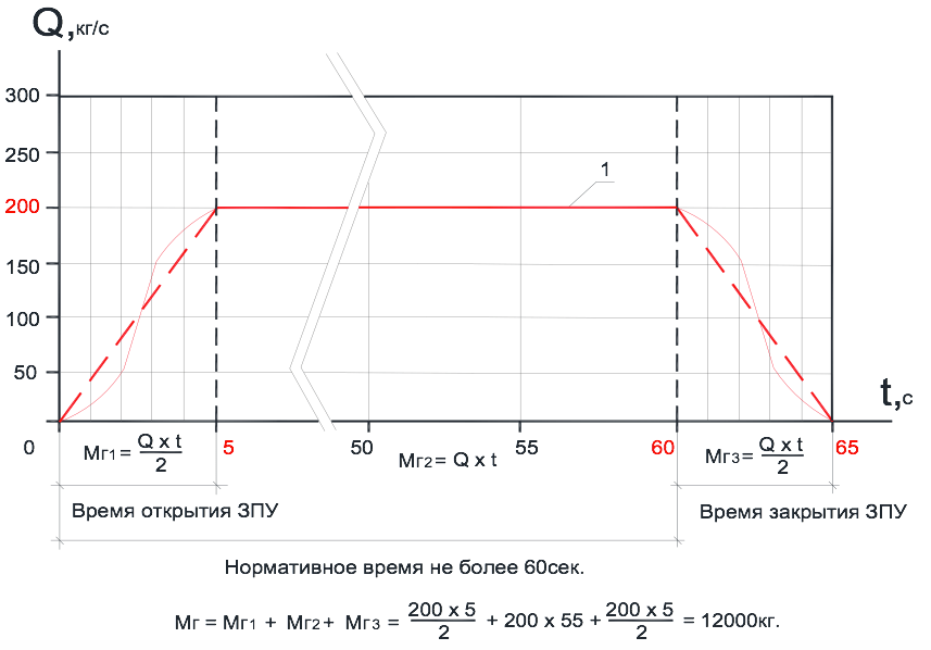 Rice-2.
1- the curve that determines the consumption of carbon dioxide over time through the CPU.
The storage of the main and reserve reserve of carbon dioxide in isothermal containers can be carried out in two different separate tanks or in one. In the second case, there is a need to close the shut-off and starting device after the output of the main reserve from the isothermal container during emergency Fire extinguishing in the protective room. This process is shown in the figure as an example (see RIS-2).
Using isothermal capacity MPJU "Volcano" as a centralized fire extinguishing station into several directions, implies the use of a shut-off-starting device (s) with a function open-close function to cut off the desired (calculated) amount of fire extinguishing agent for each gas fire extinguishing direction.
The presence of a large distribution network of the gas fire extinguishing pipeline does not mean that the expiration of the gas from the nozzle will not begin earlier than the CPU completely opens, therefore the opening time of the exhaust valve cannot be included in the technological inertia of the installation during the production of GOTV.
A large number of automated installations Gas fire extinguishing is used in enterprises with different technical production to protect technological equipment and installations both, with normal operating temperatures, and with a high level of operating temperatures on the working surfaces of the aggregates, for example:
Gas pumping units of compressor stations dividing by type
drive motor on gas turbine, gas engine and electric;
Compressor stations high pressure drive from the electric motor;
Generator sets with gas turbine, gas engine and diesel
drives;
Production technological equipment for compression and
preparation of gas and condensate on oil and gas condensate fields, etc.
For example, the working surface of the gas turbine drive casing for an electric generator in certain situations can reach sufficiently high heating temperatures exceeding the self-ignition temperature of some substances. When an emergency situation occurs, a fire, on this technological equipment and further eliminating this ignition using an automatic gas fire extinguishing system, there is always a possibility of recurrence, the occurrence of re-fire when contacting hot surfaces with natural gas Or turbine oil that is used in lubrication systems.
For equipment where there are hot work surfaces in 1986. VNIIPO MIA USSR For the Ministry of Gas Industry of the USSR, a document was developed " Fire protection gas-pumping units of compressor stations of main gas pipelines "(summarized recommendations). Where it is proposed to apply individual and combined fire extinguishing installations to extinguish such objects. Combined fire extinguishing installations imply two input queues into action of fire extinguishers. The list of combinations of fire extinguishers are available in a generalized methods. In this article we consider only the combined installations of gas fire extinguishing "Gas Plus Gas". The first phase of the gas fire extinguishing of the object complies with the standards and requirements of the SP 5.13130.2009, and the second queue (proceeding) eliminates the possibility of re-fire. The method of calculating the mass of gas for the second stage is given in generalized recommendations. See "Automatic gas fire extinguishing installations" section.
To start the gas fire extinguishing system of the first stage in technical installations Without the presence of people, the inertia of the gas fire extinguishing installation (gas start delay) must correspond to the time required to stop the operation of technical means and shutting down air cooling equipment. The delay is envisaged in order to prevent the depths of the gas extinguishing substance.
For the gas fire extinguishing system, the second stage recommends a passive method for preventing recurrence of re-fire recurrence. The passive method implies the inertization of the protected room for a time sufficient for the natural cooling of the heated equipment. The feeding time of the fire extinguishing agent into the protected zone is calculated and depending on the technological equipment can be 15-20 minutes and more. The operation of the second stage of the gas fire extinguishing system is carried out in the mode of maintaining a given fire extinguishing concentration. The second phase of gas fire extinguishing is included immediately at the end of the first stage. The first and second phase of gas fire extinguishing for feeding the extinguishing agent should have its own separate pipe wiring and a separate hydraulic calculation of the distribution pipe with nozzles. The time intervals, between which the opening of the cylinders of the second line of fire extinguishing and the stock of the fire extinguishing agent is determined by the calculations.
As a rule, for extinguishing above the described equipment, carbon dioxide CO 2 is used, but Claudones 125, 227ea and others can be used. Everything is determined by the value of the protected equipment, the requirements for the effects of the selected fire extinguishing agent (gas) on equipment, as well as efficiency when extinguishing. This issue lies entirely in the competence of specialists engaged in the design of gas fire extinguishing systems in this area.
The control circuit of such an automated combined gas fire extinguishing installation is rather complex and requires a very flexible logic of control and management work from the control station. It is necessary to carefully approach the choice of electrical equipment, that is, to gas fire control devices.
Now we need to consider general issues on the placement and installation of gas fire extinguishing equipment.
8.9.8 The system of distribution pipelines, as a rule, should be symmetric.
8.9.9 Internal volume of pipelines should not exceed 80% of the volume of the liquid phase of the estimated amount of GOTV at a temperature of 20 ° C.
8.11.2 Nozzles should be placed in a protective room, taking into account its geometry and ensure the distribution of GOTV all over the volume of the room with a concentration not lower than the normative.
8.11.4 The difference in the costs of GOTV between two extreme nozzles on one distribution pipe should not exceed 20%.
8.11.6 In one room (protected volume), nozzles of only one sizes should be applied.
3.78 Distribution pipe: Pipeline on which rods, sprayers or nozzles are mounted.
3.11 Branch of the distribution pipeline: Section of a row of a distribution pipe located on one side of the feed pipeline.
3.87 Row of distribution pipeline: A combination of two branches of the distribution pipe located on one line from two sides of the supply pipeline.
Increasingly when agreeing project documentation on gas fire extinguishing have to deal with different interpretation Some terms and definitions. Especially if the axonometric scheme of pipeline layout for hydraulic calculations sends the customer himself. In many, the organization of gas fire extinguishing systems and water fire extermination are among the same specialists. Consider two layout of gas fire extinguishing pipes, see Fig-3 and Rice-4. The "comb" type scheme is mainly used in water fire extinguishing systems. Both schemes shown in the figures are used in the gas fire extinguishing system. There is only a restriction for the "comb" type scheme, it can only be used to extinguish carbon dioxide (carbon dioxide). The regulatory time of carbon dioxide comes into a protected room is no more than 60 seconds, and it does not matter this modular or centralized installation of gas fire extinguishing.
The fill time of the carbon dioxide of the entire pipeline depending on its length and diameters of the tube can be 2-4 seconds, and then the entire pipeline system to distribution pipelines on which nozzles are converted, both in the system, water fire extinguishing in the "feed pipe". Subject to all rules of hydraulic calculation and proper selection The internal diameters of the pipes will be carried out by the requirement in which the difference in the costs of GOTV between two extreme nozzles on one distribution pipe or between two extreme nozzles on the two extreme rows of the supply pipeline, such as Row 1 and 4, will not exceed 20%. (See Catching Clause 8.11.4). The operating pressure of carbon dioxide in front of the nozzles will be approximately the same, which will ensure the uniform consumption of the fire extinguishing agent of the step through all the nozzles over time and the creation of a regulatory concentration of gas at any point of the protected room after a period of 60 seconds. Since the start of installing gas fire extinguishing.
Another case of a variety of fire extinguishing substances - chladones. The regulatory time of the reference to the protected room for modular fire extinguishing is not more than 10 seconds, and for centralized installation no more - 15 seconds. etc. (See SP 5.13130.2009).
fire extinguishingaccording to the "comb" type scheme.

Rice-3.
Hydraulic calculation with gas refrigeric gas (125, 227EA, 318C and FC-5-1-12) For an axonometric scheme for wiring a "comb" type, the main requirement of the ruled rules is ensuring a uniform consumption of fire extinguishing agent through all nozzles and ensure the distribution of GOTOS throughout the volume of the protected room with a concentration is not lower than the normative (see sawing clause 8.11.2 and paragraph 8.11.4). The difference in consumption of the GOTS family of chladone through the nozzles between the first and last rows can reach the values \u200b\u200bof 65% in the place of permissible 20%, especially if the number of rows on the supply pipeline reaches 7 pcs. and more. Obtaining such results for the gas of the chladone family can be explained by the process physics: the process of the process in time, the fact that each subsequent row takes part of the gas on itself, gradually increasing the length of the pipeline from the row to the row, the dynamics of resistance to the gas movement through the pipeline. So the first row with nozzles on the supply pipeline is in more favorable conditions Work than the last row.
The rule says that the difference in the costs of the step between two extreme nozzles on one distribution pipeline should not exceed 20% and say nothing about the consumption difference between rows on the feed pipeline. Although another rule says that nozzles should be placed in a protective room, taking into account its geometry and ensure the distribution of GOTV all over the volume of the room with a concentration not lower than the normative.
Gas installation pipeline layout plan
Fire extinguishing on a symmetric scheme.

Rice-4.
How to understand the requirement of the array of rules, the system of distribution pipelines, as a rule, should be symmetric (see Catching 8.9.8). The "Comb" type pipeline layout system Installation of gas fire extinguishing also has a symmetry relative to the feed pipeline and at the same time does not provide the same gas consumption of the chladone brand through the nozzles throughout the volume of the protected room.
On Figa-4 shows a pipeline wiring system for installing gas fire extinguishing on all symmetry rules. This is determined by three features: the distance from the gas module to any nozzle has one and the tight length, the diameters of the pipes to any nozzle are identical, the number of bends and their direction is similar. The difference in gas costs between any nozzles is practically zero. If the architecture of the protected room is necessary, some kind of distribution pipeline with a nozzle to lengthen or move to the side, the cost difference between all the nozzles will never go beyond 20%.
Another problem for gas fire extinguishing installations is the large height of the protected rooms from 5 m. And more (see RIS-5).
AXONOMOMETRIC SCHEME OF THE GAS FIRE PIPERING PUBLISHin the room one volume with a large height of the ceilings.

Rice-5.
This problem occurs when protected industrial enterpriseswhere production workshops Ceiling to be protected can have ceilings up to 12 meters high, specialized archives buildings, with ceilings reaching 8 meters and above, hangars for storage and maintenance of various special equipment, gas pumping stations and petroleum products, etc. Generally accepted maximum height Installations Nozzle relative to the floor in a protective room, widely used in gas fire extinguishing installations, as a rule, is not more than 4.5 meters. It is at this height that the developer of this equipment and checks the work of its nozzle for compliance with its parameters with the requirements of SP 5.13130.2009, as well as the requirements of other regulatory documents of the Russian Federation on fire safety.
With high height production premises, for example, 8.5 meters, the technological equipment itself will definitely be located at the bottom at the production site. For volumetric Installation of gas fire extinguishing in accordance with the rules of the SP 5.13130.2009 Nozzles should be located on the ceiling of the protected room, at a height of not more than 0.5 meters from the ceiling surface in strict accordance with their technical parameters. It is clear that the height of the production premises is 8.5 meters does not match technical characteristics nozzle. The nozzles should be placed in the protected area, taking into account its geometry and ensure the distribution of GOTV all over the volume of the room with a concentration not lower than the normative (see sawing. 8.11.2 from SP 5.13130.2009). The question of how long the regulatory concentration of gas will be equalized in time throughout the volume of the protected room with high ceilings, and what rules it can be adjusted. One solution to this question is a conditional division of the total amount of protected premises in height into two (three) equal parts, and on the boundaries of these volumes every 4 meters in the direction down the wall symmetrically set additional nozzles (see RIS-5). Additionally, the installed nozzles make it possible to quickly fill the volume of the protected room with a fire extinguishing agent with the provision of a regulatory concentration of gas, and that much more importantly ensure the fast supply of the extinguishing agent to technological equipment at the production site.
Submitted pipe wiring diagram (see Riga-5) is more convenient on the ceiling to have nozzles with spraying gun by 360o, and on the walls of the nozzle with side spraying of GOTV on the 180-1 single size and equal to the calculated area of \u200b\u200bholes for spraying. As the rule is read in one room (protected volume), nozzles of only one sizes should be applied (see sawing section 8.11.6). True, the definition of the term nozzles of one size in SP 5.13130.2009 is not given.
For hydraulic calculation of the distribution pipe with nozzles and mass calculation need quantity A gas extinguishing agent for creating a regulatory concentration in the protected amount, modern computer programs are used. Earlier, this calculation was made in manual using special approved techniques. It was difficult and long in time by action, and the result was quite greatest. To obtain reliable results of the hydraulic calculation of the pipe wiring, required great experience Man dealing with calculations of gas fire extinguishing systems. With the advent of computer and training programs, hydraulic calculations have become available to a large circle of specialists working in this area. Computer program "Vector", one of the few programs allowing you to optimally solve all sorts complex tasks In the field of gas fire extinguishing systems with minimal loss of time for calculations. To confirm the reliability of the calculation results, the verification of hydraulic calculations was carried out on the computer program "Vector" and a positive expert opinion was obtained No. 40 / 20-2016 of 03/31/2016. The Academy of GPS of the Emergencies Ministry of Russia for the use of the system of hydraulic calculations "vector" in the gas fire extinguishing facilities with the following fire extinguishers: Cold 125, Cladon 227EA, Cladon 318c, FC-5-1-12 and CO2 (carbon dioxide) production of LLC ASPT SpecialAvtomatika.
Computer program of hydraulic calculations "Vector" frees the designer from routine work. It contains all the rules and rules of the joint venture 5.13130.2009, it is within these restrictions that calculations are performed. A person inserts only its source data into the program to calculate and makes edits if the result is not satisfied.
Finally I would like to say, we are proud that in recognition of many specialists, one of the leading Russian manufacturers of automatic gas fire extinguishing installations in the field of technology is LLC ASPT Special Automation.
The company designers have developed a number of modular installations for different conditions, features and functionality of protected objects. Equipment fully complies with all Russian regulatory documents. We carefully follow and study world experience in developing in our area, which allows the use of the most advanced technologies in the development of its own production facilities.
An important advantage is that our company not only designs and establishes fire extinguishing systems, but also has its own production base for the manufacture of everything necessary equipment For fire extinguishing - from modules to collectors, pipelines and nozzles for spraying gas. Own gas stations gives us the opportunity to as soon as possible Make refueling and examination of a large number of modules, as well as carry out comprehensive tests of all newly developed gas fire extinguishing systems (GPT).
Cooperation with leading world producers of fire extinguishes and manufacturers of GOTS in Russia allows LLC ASPT SpecialAvtomatik to create multidisciplinary fire extinguishing systems using the safest, highly efficient and widespread compositions (Claudones 125, 227EA, 318C, FC-5-1-12, carbon dioxide ( CO 2)).
LLC "ASPT SpecialAvtomatika" offers not one product, but a single complex is a complete set of equipment and materials, project, installation, commissioning and subsequent maintenance above the listed fire extinguishing systems. In our organization is regularly held free Training in design, installation and commissioning of equipment manufactured, where you can get the most complete answers to all the questions that arise, as well as get any consultation in the field of fodder protection.
Reliability and high quality - our main priority!
special offer for the price for users of the Bizorg site;
timely fulfillment of obligations made;
diverse payment methods.
We are waiting for your call!
To leave an application for "crimping pipelines of fire extinguishing installations" Contact the firm "LLC New wave"According to the contact data, which are indicated in the upper right corner. Be sure to specify that the organization found on the site of Bizorg.
For details on the organization, go to the upper right corner by reference with the company name. Then go to your interesting tab with the description.
If you have problems with the interaction with the "New Wave LLC" - inform the identifiers of the organization (10676) and goods / services (50780) to our user support service.
"Covering pipelines of fire extinguishing installations" can be found in the following category: "Design and maintenance of fire extinguishing systems".
Good day, all regular readers of our blog and colleagues on the workshop! Today we will discuss new certified technical solution In the field of organization of the gas fire extinguishing system. It is no secret that in itself the installation of gas fire extinguishing is a fairly costly event and the most cost of installation is of course the pipe wiring from the storage module of the fire extinguishing agent and to the nozzles of the sprayers. This is quite justified, as the pipes used to organize distribution pipelines must be thick-walled and seamless, and they are quite expensive. The range of pipes by passing diameters, which provides for one even the smallest installation of gas fire extinguishing, is partitioned, since the pipeline must "be familiarized" from the first nozzle sprayer to the next and so on. This leads to the need to order in the specification to the project, for example 6 meters of pipes of one diameter, 4 meters of pipes of another diameter and can 2 meters of pipes of the third diameter. Trading organizations, by yourself, will not sell you pieces of pipes, and it will be offered to buy pipes of each article at least one thing, i.e. 9 meters. As a result, you will remain overwhelming from the mounted pipeline that you simply throw on the garbage, although each meter of the pipe is within 300-400 rubles per meter. Well, thousands for one and a half waste already, how to say, will go to the scrap and the rare customer will compensate these costs to you. Customers love to measure the ready-made mounted tape measure, on the fact of installation and pay money only for the length of the pipeline hanging on the ceiling. Also consider all steel couplings, transitions, tees that need to be boiled to the pipeline. Consider the coupling of welded and spray nozzles, also test plugs, gasee and high-pressure gauge collectors (RVD), which are connected directly by the pipeline with a gas cylinder. All this set of elements is required for the installation of gas fire extinguishing and from purchasing this set you do not turn in any way if you mount the system in the usual design, which includes a gas panel pipeline. And now take in the hands of the price of any manufacturer of GPT systems and take a look at prices - these small items are sold quite expensive by any manufacturer, since all these parts are also certified and the manufacturer wants to "weld" on their sale. All of the above conveying to us one simple thought - the installation of gas fire extinguishing, as a rule, costs about a million rubles with installation, includes three main elements:
In general, just from all listed elements that include the installation of gas fire extinguishing, there is a total cost - approximately one million rubles to protect a small room.
In the context of everything written above, I inform all those who still do not know - a new certified gas fire extinguishing plant has appeared,which is mounted without pipelines and consists of technologically made of small Modules of the GPT, which are mounted as powder fire extinguishing modules - directly to the overlap or on the wall on the room area. Modules of the GPT are called "Zarya", with a capacity of 3; 10; 22.5 liters, certificate of conformity since December 17, 2015 On 16.12.2020. In addition, the module includes a thermal lock, which allows you to open the module autonomously, i.e. Without control start signal from the receiving and control device. This means that even if the signaling system and fire extinguishing automation will turn out to be turned off, or for a different reason will be in non-working condition at the time of the fire, the Modules of the GPT will still open from the autonomous thermal lock and will extinguish the fire. This leads to the idea that the installation of a gas fire extinguishing of a modular type (so we call) more Lye and is ready for the task in extreme conditions. The launch of the GPT modules is made similar to the launch of powder fire extinguishing modules, from 12-24 volts with a current of 0.5-1 amps, a duration of no more than 1 second, that is, the most common "C2000-ASPT", like other fire extinguishing devices, will fully cope with This task.
Passport on the gas extinguishing modules "Zarya" can be downloaded from us on the site, after reference
In addition, we assured the work, turned to the manufacturer with a request to provide typical project Saving server room (the most running), which uses the installation of a gas fire extinguishing of a modular type. The project has a specification that can be calculated and derived estimate cost Works and simply compare the obtained value with the cost of installing the usual GPT system to the same room.
Typical project you can also download on our site, after reference
It should notice that this article is in no way advertising and does not put the purpose of product promotion. I, as a designer, and as a installer, I simply give an assessment of new products and this rating is positive, since this product makes it possible to perform the same amount of work at lower materials, less labor costs and for a relatively smaller time. In my opinion, it is very good!
On this article "Installing gas fire extinguishing without pipelines" I complete. I will be glad if in this article you learned some kind of useful information. I allow copying an article to accommodate other resources on the Internet only subject to the maintenance of all the listed links to our site, I suggest you familiarize yourself with other articles of our blog on the links:
Mode of operation of light alarms
Two evacuation exits from the placement of the shopping hall
Fire alarm or fire extinguishing at the facility?
Automatic Fire Extinguishing Systems - Overview of Options
Page 10 of 14
Mounted fire extinguishing pipes after an external inspection are tested for strength and density. The test is made by the assembly organization in the presence of the customer. The external inspection is checked by the correspondence of the mounted pipelines of the project and the compliance of the quality of the work performed by the technical conditions. The strength and density of the mounted pipelines are determined by hydraulic and pneumatic tests by creating trial pressure in them. Tests are subject to the entire line - from the station to nozzles. Testing is allowed in terms of consolidation with the customer.
Before conducting tests, joints, compounds, welding places, fasteners in order to detect defects are checked: cracks, unnecessary welds, looser, etc. Purcharge is held compressed air and checking air output through all nozzles or holes, in the necessary cases - washing pipelines.
Before the start of testing, pipelines are disconnected from the fire extinguishing installation, nozzles are turned out and plugs are installed on their place.
Pipelines applying test liquid or air from pumps, compressors, cylinders, etc. Test pipelines are pre-tested by hydraulic pressure in the assembled form with -Ported by reinforcement and pressure gauges.
The test pressure of the ri, created in pipelines, should be 1.25 PP (PP - working pressure). The operating pressure (pressure) of flashes in pipelines is, MPa (kgf / cm 2): Penogen agents 0.4-0.6 (4-6), water irrigances 0.2-0.6 (2-6) carbon dioxide (gas) - 7.5 (75), Freon vapors 0.2-0.4 (2-4), nitrogen 15 (150).
Hydraulic testing of pipelines is produced in steps: the first stage is 0.05-0.2 MPa (0.5-2 kgf / cm 2); the second is 0.5 pp; Third - to PP; Fourth - to Ri.
Hydraulic tests on the intermediate levels of pressure lifting should have an excerpt for 1-3 minutes, during which the lack of pressure in the pipelines is set to the pressure gauge.
Under the test pressure, pipelines are maintained for 5 minutes, then the pressure smoothly decreases to the worker and a thorough inspection of pipelines is made.
Gas pipelines They are considered suitable for exploitation if the pressure drops will not be more than 10% of the PP in terms of PR and the pressure drops and changes in the shape, cracks and leaks will not be revealed during the inspection.
Water pipelines I. foam fire extinguishing It is maintained under a pressure of 1.25 pp [but no less pp + + 0.3 mp (3kgs / cm 2)] for 10 minutes, then the pressure is gradually decreasing to the RR and a thorough inspection of all welded connections and seats adjacent to them are made. The network of pipelines is considered to be withstood hydraulic test if there are no signs of rupture, leaks in welded joints and visible residual deformations.
Flushing and hydraulic testing of pipelines are carried out under conditions that exclude the danger of their freezing.
At the end of the tests from the pipelines, the test liquid (water) is descended and in the necessary cases it is cleaned with compressed air.
Tests on the density of pipelines of pneumatic pressure pipelines are allowed only after testing them for strength hydraulic pressure. With pneumatic tests, air or inert gas is used as a test medium, the pressure in the pipeline rises to 0.2 MPa (2 kgf / cm 2).
Pipelines are considered withstanding the density test if the pressure drops will not be more than 0.02 MPa (0.2 kgf / cm 2) during the exposure under pressure within 24 hours (0.2 kgf / cm 2) and the release, cracks and leaks will not be detected during the inspection. To check leaks, aqueous foaming emulsion of soap compositions is used.
The elimination of defects on the pipeline during pneumatic tests, somehow: the cutting of the pipes with a hammer, compaction compaction, seams, is dangerous and strictly prohibited.
Conducting hydraulic and pneumatic testing of pipelines is issued by acts (see applications 1.2).
Russian joint stock
SOCIETYEnergy
ANDElectrification «
UESRussia»
DepartmentSCIENCEANDTechniques
TypicalInstruction
BY
OperatingAutomatic
Installations
WaterFire extinguishing
RD 34.49.501-95
OrgRes.
Moscow 1996
Designed Joint-Stock Company "Firm for commissioning, improving the technology and operation of power plants and networks" OrGRES ".
Performers YES. Odsery, A.N. Ivanov, A.S. Kozlov, V.M. Starikov
Agreed With the Department of General Inspection Inspectorate for Power Plants and Networks RAO "UES of Russia" on December 28, 1995
Head of N.F. Gorez
Approved Department of Science and Technology RAO "UES of Russia" on December 29, 1995
Head of A.P. Bersenev
|
Typical instruction manual for automatic water fire extinguishing installations |
RD 34.49.501-95 |
The validity period is set
from 01/01/97
In this Typical instruction The main requirements for the operation of the technological equipment of water fire extinguishing installations used in energy enterprises are given, and the order of washing and crimping the pipelines of fire extinguishing installations is presented. The volume and order of controlling the state of technological equipment, the timing of the revision of the entire fire extinguishing equipment equipment and are given the basic troubleshooting guidelines.
The responsibility for the operation of fire extinguishing installations is established, the necessary working documentation and staff training requirements are provided.
The basic requirements of safety equipment are indicated during the operation of fire extinguishing installations.
Forms of acts of flushing and crimping pipelines and firing tests are given.
With the output of this typical instruction, the "typical instruction manual for automatic fire extinguishing installations: Ti 34-00-046-85" (M.: SPO UnionChenergo, 1985).
1.1 . The typical instruction establishes the requirements for the operation of industrial equipment of water fire extinguishing equipment and is required for the heads of energy enterprises, heads and individuals appointed for the operation of fire extinguishing facilities.
1.2 . The technical requirements for the operation of the technological equipment of the foam fire extinguishing installations are set out in the "Instructions for the operation of fire extinguishing installations with the use of air-mechanical foam" (M.: SPO OrGRES, 1997).
1.3 . When operating fire alarm automaticfire extinguishing installations (AUP) should be guided by "typical instruction manual for automatic fire alarm installations on energy enterprises" (M.: SPO OrGRES, 1996).
This typical instruction adopted the following reductions.
OHP - installation of water fire extinguishing,
AUP - automatic fire extinguishing installation,
AVUP - automatic waterfront installation,
PPS - fire alarm console,
Puez - electrotane control panel,
Pupn - fire pump control panel,
Pi - Fire Detector,
Mon - Fire Pump,
OK - check valve,
DV - Drencher Water,
DVM - Drencher Water Modernized,
ODD - Penno-Drencher roster.
2.1 . Based on this typical instruction, an organization that produced the AUP technological equipment settling, together with the energy enterprise, which establishes this equipment, should develop local instructions for the operation of technological equipment and AUD devices. If the commissioning was carried out by energy enterprise, the instruction is developing the staff of this enterprise. Local instructions should be developed at least one month before acceptance of the AUP into operation.
2.2 . The local instructions should take into account the requirements of this typical instruction and the requirements of factory passports and instructions for the operation of equipment, instruments and equipment that are part of the AVUP. Reducing the requirements set forth in the specified documents is not allowed.
2.3 . Local instructions should be reviewed at least once every three years and each time after the reconstruction of the AUP or in case of changes in operating conditions.
2.4 . Acceptance of the AUP into operation should be carried out as part of the representatives:
energy Power Supplies (Chairman);
project, installation and applied organizations;
state fire supervision.
The program of work of the Commission and the act of acceptance must be approved by the main technical leader of the enterprise.
3.1 . When operating the technological equipment of water fire extinguishing equipment, energy enterprises must comply with the relevant safety requirements specified in PTE, PTB, as well as in factory passports and instructions for use of specific equipment.
3.2 . With maintenance and repair of the AUP, when visiting the premises, protected by AUP, the automatic control of the specific distribution pipeline of this direction should be translated into manual (remote) before exiting the room of the last person.
3.3 . Cooking with water pipelines should be carried out only according to the approved program in which measures should be included, providing staff protection from a possible rupture of pipelines. Must be provided full removal Air from pipelines. Combine work on crimping with other works in the same room is prohibited. If crimping is carried out by contracting organizations, then work is performed by tolerance. The implementation of these works by operational or repair personnel of the energy enterprise is issued by written orders.
3.4 . Before the start of work, the staff employed by crimping should be instructed by safety in the workplace.
3.5 . During the crimping in the room there should be no extraneous persons. Pressing should be carried out under the control of the responsible person.
3.6 . Repair work on technological equipment should be carried out after taking pressure from this equipment and the preparation of the necessary organizational and technical measures established by the current PTB.
4.1 . Installation of water fire extinguishing consists of:
water supply (reservoir, reservoir, urban water supply, etc.);
fire pumps (designed for fence and supply water into pressure pipes);
suction pipelines (connecting the water source with fire pumps);
pressure pipelines (from the pump to the control node);
distribution pipelines (laid within the protected room);
control units installed at the end of pressure pipelines;
rods.
In addition to the above, based on design solutions, the fire extinguishing scheme may include:
tank with water for filling fire pumps;
pneumoBack to maintain constant pressure in the fire extinguishing network;
compressor for feeding the pneumatic air;
trigger cranes;
check valves;
dosage washers;
pressure switch;
manometers;
vacuum;
level gauges for measuring levels in tanks and pneumatic bodies;
other instruments of alarm, control and automation.
The schematic diagram of the installation of water fire extinguishing is shown in the figure.
4.2 . After the installation of the installation work, suction, pressure and distribution pipes must be washed and subjected to hydraulic tests. The results of washing and crimping should be decorated with acts (applications and).
If possible, it is possible to check the effectiveness of the fire extinguishing installation by organizing the extinguishing of the artificial focus of the fire (application).
4.3 . When washing pipelines, water should be served with them ends towards the control units (in order to prevent the clogging of pipes with a smaller diameter) at a speed of 15-20% more water velocity during a fire (determined by the calculation or recommendations of project organizations). Flushing should be continued to the steady appearance of pure water.
If it is impossible to flush individual sections of pipelines, it is allowed to purge with dry, clean, compressed air or inert gas.
Concept of water fire extinguishing installation scheme:
1 - water storage tank; 2 - fire pump (PN) with electric drive; 3 - pressure pipe; 4 - suction pipe; 5 - distribution pipe; 6 - fire detector (PI); 7 - control node; 8 - manometer; 9 - check valve (OK)
Note.Reserve fire pump with reinforcement is not shown.
4.4 . Hydraulic testing of pipelines must be carried out under a pressure of 1.25 worker (P), but not less p + 0.3 MPa, for 10 minutes.
To disable the test area from the rest of the network, you must install the deaf flanges or plugs. It is not allowed to use for this purpose available control nodes, repair valves, etc.
After 10 minutes, test pressure should be gradually reduced to the worker and make a thorough inspection of all welded connections and segments adjacent to them.
The network of pipelines is considered to be withstood hydraulic test if there are no signs of breaking, leaks and droplets in welded joints and on the main metal, visible residual deformations.
Measure pressure follows two pressure gauges.
4.5 . Flushing and hydraulic tests of pipelines should be carried out under conditions that exclude their freezing.
It is forbidden to frish from open trenches with pipelines undergoing strong frosts, or a frustration of such trenches with fatty soil.
4.6 . Automatic water fire extinguishing installations must operate in automatic start mode. For the period of stay in cable structures of personnel (bypass, repair work, etc.) Start of installations should be transferred to manual (remote) inclusion (p. ).
5.1 . Organizational events
5.1.1 . Persons responsible for the operation, conducting the capital and current repair equipment of the fire extinguishing equipment, are appointed by the head of the energy enterprise, which also approves graphics of technical supervision and equipment repair.
5.1.2 . The person responsible for the constant readiness of the fire extinguishing equipment technological equipment must know the principle of the device and the procedure for the operation of this equipment, as well as to have the following documentation:
project with changes made during installation and adjustment of fire extinguishing installation;
factory passports and operational instructions on equipment and devices;
this typery instruction and local instruction manual for process equipment;
acts and protocols of installation and commissioning, as well as testing of the operation of technological equipment;
play-schedules of maintenance and repair of technological equipment;
"Maintenance of maintenance and repair of fire extinguishing installation".
5.1.3 . Any deviations from the accepted draft scheme, replacing equipment, an additional installation of irrigators or their replacement with rods with a large nozzle diameter must be previously agreed with the project institute - the author of the project.
5.1.4 . To control the technical condition of technological equipment for fire extinguishing installation, a "log of maintenance and repairing installation of fire extinguishing installation should be conducted, in which the date and time of checking, who conducted the verification, detected faults, their nature and the time of their elimination, time of forced disabling and inclusion Fire extinguishing installations, conducted testing of the entire installation or individual equipment. Approximate log shape is provided in the application. .
At least once a quarter with the content of the magazine should be met by receipt of the main technical leader of the enterprise.
5.1.5 . To verify the readiness and effectiveness of AVP, once every three years, a complete revision of the technological equipment of this installation should be carried out.
During the revision, in addition to the main work, the pressure testing pipeline is carried out and washing (or purge) and the pressure testing of distribution pipelines (PP), which are in the most aggressive medium (dampness, gas and dust) are carried out at two to three directions.
If deficiencies are found, it is necessary to develop activities that ensure full elimination of their deadlines.
5.1.6 . Automatic fire extinguishing installation in accordance with the schedule approved by the head of the appropriate workshop, but at least once every three years should be tested (tested) on a specially developed program with a real launch of them to work, provided that it will not entail a stop of technological equipment or all production process. During testing in the first and last ripples, water pressure and irrigation intensity should be checked.
Testing should be carried out with a duration of 1.5 - 2 minutes with the inclusion of serviceable drainage devices.
According to the results of testing, the act or protocol must be drawn up, and the fact of testing is registered in the "Maintenance and repairing and repairing of fire extinguishing installation".
5.1.7 . Checking the operation of AWP or individual types of equipment should be carried out during the output for repair, maintenance of the protected room and the technological installation.
5.1.8 . To store spare equipment, equipment parts, as well as devices, tools, materials, appliances required for control and organization repair work AUVP, a special room must be allocated.
5.1.9 . The technical capabilities of AWP should be made to the operational plan for extinguishing the fire in this energy enterprise. During the fire-fighting training, it is necessary to expand the range of personnel, which knows the purpose and the AVU device, as well as the order of bringing into action.
5.1.10 . Personnel serving compressors and pneumatic boys AWP should be trained and certified in accordance with the requirements of the Gosgortkhnadzor Rules.
5.1.11 . The person responsible for the operation of the technological equipment of the fire extinguishing installation should organize classes with personnel allocated to control the work and maintenance of this equipment.
5.1.12 . In room pumping station AVUP should be posted: Instructions on the procedure for inclusion of pumps and open shut-off valves, as well as principled and technological schemes.
5.2 . Technical Requirements for AVUP
5.2.1 . Pads to the building (room) of the pumping station and the installation of fire extinguishing, as well as approaches to pumps, pneumatic, compressor, control nodes, pressure gauges and other fire extinguishing equipment, should always be free.
5.2.2 . The existing fire extinguishing installation must be sealing in the working position:
hatches of reservoirs and containers for storing water stocks;
control units, valves and hand-inclusion cranes;
pressure switch;
running taps.
5.2.3 . After the fire extinguishing installation is triggered, its performance must be fully restored no later than 24 hours.
5.3 . Water storage tanks
5.3.1 . Verification of water level in the tank should be carried out daily with registration in the "Maintenance and repair journal of fire extinguishing installation".
When a decrease in the water level due to evaporation, it is necessary to add water, if you have leaks, set the place of damage to the tank and eliminate leaks.
5.3.2 . The operation of the automatic level gauge in the tank must be checked at least once every three months at the plus temperature, monthly - when negative temperature And immediately in case of doubt in good operation of the level gauge.
5.3.3 . The tanks must be closed to access unauthorized persons and sessured, the integrity of the seal is checked during the inspection of the equipment, but at least once a quarter.
5.3.4 . Water in the reservoir should not contain mechanical impurities that can score pipelines, dosage washers and rods.
5.3.5 . To prevent the rotation and flowering of water, it is recommended to disinfect with chlorine lime at the rate of 100 g of lime per 1 m 3 of water.
5.3.6 . Replacing water in the tank is needed annually in autumnshe is time. When the water is replaced, the bottom and inner walls of the tank are cleaned from dirt and growths, damaged color is restored or fully updated.
5.3.7 . Prior to the start of frosts, the gaps between the lower and the top covers of the hatch must be filled with insulated material.
5.4 . Suction pipe
5.4.1 . Once a quarter, the state of the inputs, shut-off valves, measuring instruments and a water intake well is checked.
5.4.2 . Prior to the onset of frost, the valve in the water intake should be examined, if necessary, repaired, and the well was insulated.
5.5 . Pumping station
5.5.1 . Before testing the pumps, you need to check: tightening the glands; Lubrication level of bearings baths; correctness of the tightening of the foundation bolts, nuts cover of pumps and bearings; Connections of the pipeline on the suction side and the pumps themselves.
5.5.2 . Once a month, pumps and other equipment of the pumping station should be seen, cleaned from dust and dirt.
5.5.3 . Each fire pump is at least two times a month should be included to create the required pressure, which is recorded in the operational journal.
5.5.4 . At least once a month, the reliability of the transfer of all fire pumps to the main and backup power supply with the registration of results in the operational journal should be checked.
5.5.5 . If there is a special tank for the pump bay, the latter should be inspected annually and painted.
5.5.6 . Once every three years, pumps and engines according to p. . This typical instruction should be conducted by revision, during which all available disadvantages are eliminated.
Repair and replacement of workmen, checking the seals is carried out as needed.
5.5.7 . Pumping station must be kept clean. In the absence of duty, it must be fixed on the lock. One of the spare keys should be stored on the control panel, which should be indicated on the doors.
5.6 . Press and distribution pipelines
5.6.1 . Once a quarter must be checked:
lack of leaks and pipelines;
the presence of a constant slope (not less than 0.01 for pipes with a diameter of up to 50 mm and 0.005 for pipes with a diameter of 50 mm or more);
state of fixtures of pipelines;
lack of touches of electrical storage and cables;
coloring condition, no dirt and dust.
Detected disadvantages that may affect the reliability of the installation operation must be eliminated immediately.
5.6.2 . Pipeline should be in constant readiness to action, i.e. filled with water and be under operating pressure.
5.7 . Control nodes and shut-off valves
5.7.1 . For AWP transformers and cable structures in the locking and starting devices, steel reinforcement electrified gate valves should be applied with automotive stamps of 30C 941NG; 30C 986NG; 30C 996NZH with a working pressure of 1.6 MPa, repair valves with manual brand 30s 41nzh with a working pressure of 1.6 MPa.
5.7.2 . The status of control nodes and shut-off reinforcement, the presence of a seal, pressure values \u200b\u200bbefore and after control nodes must be monitored at least once a month.
5.7.3 . Once in the first half of the year, the electrical circuit of the control of the control unit with its automatic inclusion from the fire detector with a closed valve is carried out.
5.7.4 . The location of the control unit should be well lit, the inscriptions on pipelines or special stencils (node \u200b\u200bnumber, protected area, the type of irriments and their number) must be made of implanted bright paint and look through well.
5.7.5 . All damage to the valves, valves and check valves, which can affect the reliability of the operation of the fire extinguishing installation, must be eliminated immediately.
5.8 . Santers
5.8.1 . As water irrigances for automatic fire extinguishing of transformers, ODDR-15 irrigances with water pressure in front of the rods in the range of 0.2 - 0.6 MPa are used; For automatic fire extinguishing of cable structures, dv rods are used, DVM with a working pressure of 0.2 - 0.4 MPa.
5.8.2 . When examining the equipment of distribution devices, but at least once a month, the rods must be examined and cleaned from dust and dirt. When a malfunction or corrosion is detected, measures should be taken to eliminate them.
5.8.3 . When carrying out repair work, the rods must be protected from plasters and paints on them (for example, polyethylene or paper caps, etc.). Detected after repair traces of paint and solution must be removed.
5.8.4 . It is forbidden to install instead of defective jams and plugs.
5.8.5 . To replace faulty or damaged rods, a reserve 10 - 15% of the total number of installed irrigances must be created.
5.9 . Pneummobac and compressor
5.9.1 . The inclusion of the pneumatic to work should be carried out in the following sequence:
fill the pneumobac with water by approximately 50% of its volume (the level is controlled by water glass);
turn on the compressor or open the valve on the compressed air pipe;
pressure in the pneumobacker to raise to the worker (controlled by the pressure gauge), after which the pneumatic bodies connect to the pressure pipe, creating a working pressure in it.
5.9.2 . Every day an external inspection of the pneumatic tube should be carried out, check the water level and air pressure in the pneumatic tube. With a decrease in air pressure by 0.05 MPa (with respect to the worker), its swap is produced.
Once a week, the compressor is tested at idle.
5.9.3 . Maintenance Pneumatic and compressor, held once a year, includes:
emptying, inspection and cleaning of pneumatic:
removing and checking on the stand safety valve (with malfunction to replace new);
color surface of the pneumatic (on the surface indicate the repair date);
detailed compressor inspection (replace worn parts and fittings);
execution of all others technical requirementsstipulated by factory passports and operating instructions for pneumatic and compressor.
5.9.4 . Turning off the pneumatic from the fire extinguishing scheme is prohibited.
5.9.5 . The inspection of the pneumatic bodies is made by a special commission with the participation of representatives of the State Mountain Supplies, the local bodies of the state fire supervision and this energy enterprise.
Note.The compressor should be turned on only manually. At the same time, it is necessary to monitor the level in the pneumatic, since automatic inclusion The compressor is possible to extrude water water from pneumatic and even from the network.
5.10 . Manometers
5.10.1 . The correctness of the testimony of the work of the pressure gauges installed on the pneumators should be checked once a month mounted on pipelines - once in a half.
5.10.2 . Full checking on the fire extinguishing installation of all pressure gauges with their sealing or branding should be made annually in accordance with the current position.
6.1 . During the repair of technological equipment, fire extinguishing equipment should be guided by the requirements of the passport, the instructions for the operation of the specific equipment, the requirements of the relevant norms and technical conditions, as well as the requirements of this typical instruction.
6.2 . When replacing the pipeline section on bending, the minimum radius of the inner bend curve steel pipes must be forbending them in a cold state of at least four outer diameters, in the hot condition - at least three.
On the curved part of the pipe should not be folds, cracks or other defects. Ovality in bending places is allowed no more than 10% (determined by the ratio of the difference between the greatest and smallest outer diameters of the curved tube to the outer diameter of the pipe to bend).
6.3 . The difference and displacement of the edges of the jammed pipes and parts of the pipelines should not exceed 10% of the wall thickness and should be no more than 3 mm.
6.4 . The edges of the welded pipe ends and the surface adjacent to them before welding must be cleaned of rust and dirt on a width of at least 20 mm.
6.5 . The welding of each joint must be performed without interruptions until the entire joint is fully welding.
6.6 . The welded joint of the pipes should be blown when the following defects are found:
cracks overlooking the surface of the seam or base metal in the welding zone;
slops or subsoring in the zone of transition from the base metal to the deposited;
burns;
the non-uniformity of the weld in width and height, as well as deviations from the axis.
6.7 . In especially raw premises With a chemically active medium of the pipeline fastening, the steel profiles of at least 4 mm thick should be performed. Pipelines and fastening designs should be covered protective varnish or paint.
6.8 . Compounds of pipelines with open gasket should be located outside the walls, partitions, overlaps and other building structures.
6.9 . Fastening pipelines to building construction structures should be carried out by normalized supports and suspensions. The welding of pipelines directly to the metal structures of buildings and structures, as well as elements of technological equipment is not allowed.
6.10 . Welding supports and suspension to building structures should be carried out without weakening their mechanical strength.
6.11 . Chers and curvatures of pipelines are not allowed.
6.12 . Every turn of the pipeline longer than 0.5 m shouldhave a mount. The distance from the pendants to the welded and threaded joints of the pipes should be at least 100 mm.
6.13 . The newly installed rods must be cleaned of preservative lubrication and tested by hydraulic pressure of 1.25 MPa (12.5 kgf / cm 2) for 1 min.
The average service life of the rods is defined at least 10 years.
6.14 . The performance of the air rods, DVM and ODDR-15 is given in Table. .
Table 1
|
The diameter of the outlet, mm |
The performance of the rod, l / s, at a pressure of MPa |
||||
|
DV-10 and DVM-10 |
|||||
|
ODDR-15 |
|||||
7.1 . Possible malfunctions in the installation of water fire extinguishing and recommendations for their elimination are given in Table. .
table 2
|
Water does not come out of the rods, the pressure gauge shows normal pressure |
Valve closed |
Open valve |
|
Started check valve |
Open check valve |
|
|
Scored pipeline |
Clear pipeline |
|
|
Irrigated irrigation |
Liquid clogging |
|
|
Water does not come out of the rods, the pressure gauge does not show pressure |
Did not turn on the fire pump |
Enable fire pump |
|
Closed valve on the pipeline from the suction side of the fire pump |
Open valve |
|
|
Air seats occurs on the suction side of the fire pump |
Eliminate compound faults |
|
|
Wrong direction of rotation of the rotor |
Switch the phases of the electric motor |
|
|
Accidentally open a valve of another direction |
Close the valve on the other direction |
|
|
Water leak through welded seams, in places connecting controls and rods |
Non-quality welding |
Check the quality of welds |
|
Gasket was worn out |
Replace strip |
|
|
Weakened protracted bolts |
Tighten the bolts |
|
|
There is no testimony of the manometer |
No pressure in the pipeline |
Restore pressure in the pipeline |
|
The front entrance was clogged |
Remove the pressure gauge and clean the hole |
|
|
Ringing contacts manometer |
Contamination of the contacts of the manometer |
Remove glass pressure gauge and clean the contacts |
ACT
|

