INSTRUCTIONS AND PROPHECIES OF THE Blessed MOTHER ALIPIA GOLOSEEVSKY, Kyiv...


The section is very easy to use. In the proposed field, just enter the desired word, and we will give you a list of its meanings. I would like to note that our site provides data from various sources - encyclopedic, explanatory, word-building dictionaries. Here you can also get acquainted with examples of the use of the word you entered.
benchmark
benchmark, m. (fr. repire) (geodes.). A firmly fixed staking platform, with a precisely defined height above sea level, serving as a starting point or a reference point for leveling.
benchmark
m. A sign fixed on the ground indicating a certain absolute height of a given point (in geology).
m. The set of two (on the plane) or three (in space) vectors with a common origin, not lying on the same straight line and taken in a certain order (in mathematics).
m. An auxiliary point at which the gun is sighted for the subsequent transfer of fire to the target (in artillery).
benchmark
in geodesy - a sign of a point with a known absolute height, a metal disk with a ledge (or with a hole - a mark), fixed in the walls of long-term structures, or a concrete monolith laid in the ground.
benchmark
REPER (French repere) in space (on a plane) is a set of three (two) vectors with a common origin, not lying in the same plane (on the same straight line) and taken in a certain order.
Benchmark
rapper
Benchmark (geodesy)
rapper(from - label, sign, starting point) in geodesy - a sign that fixes a certain point on the earth's surface with a known absolute height. This height is determined by leveling with respect to the original level surface. A metal disk 5 centimeters in diameter with a number and an indication of the department is fixed on the benchmarks. AT Russian Federation it is customary to calculate the heights of benchmarks relative to the zero mark of the Kronstadt footstock.
Reference (geometry)
rapper (sign, starting point) is the set of a point of the manifold and the basis of the tangent space at this point.
Frame (affine geometry)
rapper(from - sign, starting point) or point basis affine space - a generalization of the concept of a basis for affine spaces.
An affine space frame A, associated with the vector space V dimensions n, is a set of points O ∈ A(origin) and an ordered set of n linearly independent vectors e, …, e ∈ V(that is, the basis in n-dimensional vector space V). This is equivalent to giving an ordered set of n+ 1 affine independent points O, P, …, P ∈ A. In this case, obviously, the vectors $e_1 = \vec(OP_1), \ldots, e_n = \vec(OP_n)$.
Coordinates points X ∈ A relative frame ( O; e, …, e) are the coordinates of the vector $\vec(OX)$ with respect to the basis e, …, e. In the same way as when choosing a basis in a vector space, any vector of this space is given by its coordinates, any point of an affine space is given by its coordinates relative to the selected frame. If with respect to the benchmark ( O; e, …, e) dot X ∈ A has coordinates ( x, …, x), and the point Y ∈ A- coordinates ( y, …, y), then the vector $\vec(XY)$ has with respect to the basis e, …, e coordinates ( y − x, …, y − x).
Benchmark ( O; e, …, e) is called orthogonal (orthonormal) if the corresponding basis e, …, e is orthogonal.
Benchmark (artillery)
rapper- a real or conditional point on the ground used for zeroing in artillery pieces. These benchmarks are used to transfer fire to real targets without first zeroing them in. There are two types of benchmarks: real and fictitious.
At the top of Iremel, one cannot find a single benchmark, no wreckage of the trigapoint, just various rubbish dragged here by tourists.
A hyperluminal exhaust is an explosion with a capacity of tens of megatons, carrying a potential danger for lighthouses, highway benchmarks and other ships.
Students, graduate students, young scientists who use the knowledge base in their studies and work will be very grateful to you.
Posted on http://allbest.ru
Reference points in geodesy
Benchmark (from French repere - sign, starting point) - a sign that fixes a point on the earth's surface, the height of which relative to the original level surface is determined by leveling.
In the Russian Federation, the heights of the benchmarks are calculated relative to the zero of the Kronstadt footstock.
The benchmarks of the state leveling network serve as starting (reference) points for determining the heights of intermediate points of the earth's surface when topographic surveys and various kinds survey work, and are also used for scientific purposes when studying the difference in sea levels.
Benches according to their importance are divided into:
1) age-old
2) fundamental
3) privates.
Centuries-old benchmarks are distributed throughout the country, according to a special scheme, in places established by the instruction, mainly for scientific purposes. The depth of the bookmark is determined by the occurrence rocks.
The fundamental benchmarks, which are reinforced concrete pylons, are laid into the ground every 50–80 km on all leveling lines of the 1st class, as well as on the most important lines of the 2nd class and near the most important offshore water meters.
Ordinary benchmarks, laid after 5--7 km on leveling lines of all classes, are divided into ground, installed in the ground, rock (fixed in rocks) and wall, laid in the walls of capital structures.
AT hard-to-reach areas the distance between benchmarks can be increased to 6-7 km, and in seismically active areas it should be reduced to 3-3.5 km.
Wall anchors are fixed in the built-up area wherever possible. Fastening is carried out in the bearing parts of stone or concrete structures at a height of less than 0.3 m using leveling marks.
Rock benchmarks: ordinary - in design and installation are absolutely similar to the centers of the geodetic network, fundamental - are found as an exception.
Ground benchmarks: ordinary - in design and installation are absolutely similar to the GGS centers, fundamental - are a massive reinforced concrete monolith made immediately at the laying site right in the pit.
Since the fundamental benchmark can only be used for leveling I and II classes, a satellite benchmark is installed nearby, which is an ordinary benchmark, to which the mark from the fundamental benchmark is transmitted with class II accuracy and which is used instead of the fundamental one as a reference for leveling classes III and IV.
In Russia, the Baltic system of heights is used in the Far East. In the late 1980s, the mark of the Kronstadt footstock was transferred to the coast of the Far Eastern seas, the expected error was approximately 1 meter.
Types and designs of benchmarks, their manufacture and laying
The diverse physical and geographical conditions of the country determine different types benchmarks that correspond to certain areas.
A detailed description of the design of benchmarks, methods of their manufacture and laying is described in the "Rules for laying centers and benchmarks at points of geodetic and leveling networks", M., "Kartgeocenter" - "Geodesizdat".
Rock and wall benchmarks are included in the leveling lines of all classes one day after their laying, ground benchmarks on leveling lines of classes III and IV - not earlier than 15 days after backfilling the pit.
In the permafrost distribution zone, ground benchmarks laid by drilling and thawing of soil are included in leveling not earlier than two months after their laying, and by excavation - in the season preceding leveling.
On leveling lines of classes I and II, ground benchmarks, as a rule, are laid a year before leveling.
To reduce or eliminate corrosion metal parts benchmarks should be used, if possible, galvanized or enameled pipes. In case of their absence on metal pipes apply an anti-corrosion coating. An anti-corrosion coating is also applied to the surface of concrete benchmarks if they are laid in a particularly aggressive soil environment. To reduce the effect of frost heaving, the outer surfaces of the benchmarks laid in the ground must be covered with anti-heaving agents. Benchmarks are protected in accordance with the requirements of the Federal Law "On Geodesy and Cartography" and the "Regulations on Protected Zones and Protection of Geodetic Points on the Territory of the Russian Federation", approved by Decree of the Government of the Russian Federation N 1170 of October 7, 1996.
Benchmarks are subject to inspection on the ground within the time limits stipulated normative documents Roskartografiya for the survey and restoration of points of geodetic and leveling networks. stable, incompressible rocks.
Centuries-old benchmarks can be rocky and unpaved. The types of age-old benchmarks depend on the depth of the rock. The safety of the age-old benchmark is ensured by the quality of the bookmark, the quality factor of the materials from which it is made, as well as the location and external design.
If the rock is at a depth of up to 120 cm, then a group of four rock benchmarks of the 173k type (Fig. 1, a) is laid, located at a distance of 25-50 m from each other. The heights of adjacent benchmarks must differ from each other by at least 15 cm.
The benchmark consists of a brand (stainless steel or bronze) and concrete well with lid. The dimensions of the well depend on the depth of the rock. When the rock comes out to the day surface, the external dimensions of the well are 50x50 cm. If the depth of the rock is 50 cm or more, this is a well with a diameter of 100 cm.
When the rock lies at a depth of 120 to 500 cm, a century-old benchmark of type 174k is laid (Fig. 1, b), which consists of a pylon (granite or high-quality concrete) with a parallelepiped shape and a cross section of 35x35 cm, a concrete slab (anchor) with dimensions of 100x100x40 cm and a well with a diameter of more than 100 cm.
Two grades (horizontal and vertical) are cemented into the upper part of the pylon at a distance of 20 cm.
The upper end of the pylon is located at a depth of 100 cm from the ground. A concrete slab is made at the place of installation of the benchmark and the third brand is cemented into it.
Before backfilling the pit with soil and installing the well, the excesses between all grades are measured with an accuracy of 1 mm.
The benchmark in the well is covered with gravel, and at a distance of 100-150 m from it, a fundamental benchmark with a satellite is installed.
A century-old tubular benchmark of type 175k (Fig. 2) is laid at the occurrence of incompressible rocks at a depth of more than 500 cm.
The benchmark is laid in a well with a diameter of ~25 cm.
It consists of a metal pipe with a diameter of 8-15 cm with a wall thickness of at least 1 cm, buried in incompressible rocks by 120 cm.
The reference pipe ends with a steel tip at least 250 cm long with three anchor discs.
The reference pipe with the help of concrete poured into the well is fastened to incompressible rocks.
The reference pipe is located in a protective pipe with a diameter of 16-23 cm with a wall thickness of at least 1 cm. protective tube separated by an oil seal and bitumen, at the top - by a rubber diaphragm and bitumen. At the upper end of the reference tube, at a distance of 20 cm from each other, two marks of a slightly oxidizing material (horizontal and vertical) are strengthened. The upper end of the benchmark is located at a depth of 100 cm from the surface of the earth. A fundamental benchmark with a satellite is laid next to the century-old benchmark at a distance of 100-150 m.
Fundamental benchmarks
Fundamental benchmarks, depending on the laying conditions, are divided into ground benchmarks (reinforced concrete, asbestos-cement, tubular metal) and rock ones.
Fundamental benchmark type 161 op. a sign (Fig. 3) for the area of \u200b\u200bseasonal freezing of soils is made in a pit. A reinforced concrete pylon measuring 30x30 cm is integral with a concrete slab (anchor). Grades made of low-oxidizing material (bronze, stainless steel) or cast-iron grades with hemispherical inserts made of low-oxidizing material are cemented into the upper faces of the pylon and slab.
It is allowed to replace the reinforced concrete pylon with an asbestos-cement pipe with outside diameter not less than 25 cm. A metal frame is installed inside the pipe and filled with concrete.
To increase the connection of the base of the asbestos-cement pipe with the anchor at a distance of 15-20 cm from the base, two mutually perpendicular rods with a diameter of 1.0-1.5 cm and a length of 60 cm are inserted until the pipe is filled with concrete. The upper face of the concrete slab is placed 60 cm below the boundary of the largest soil freezing, and the upper part of the pylon - 100 cm below the ground.
Above the benchmark, at a depth of 30 cm from the surface of the earth, an identification mark is laid. concrete slab 30x30x10 cm in size. The benchmark is made in a pit, the depth of which corresponds to the depth of the upper edge of the slab. For a concrete slab (anchor), they dig a recess in the soil of natural density. To do this, a tetrahedral recess is made at the bottom of the pit, the side walls of which are expanded downwards (Fig. 3).
The dimensions of the slab with vertical side faces are 115x115x40 cm. sign and 114 op. the sign is shown in Fig.4. If the rock comes to the earth's surface or lies at a depth of up to 130 cm, then two grades with a height difference of more than 100 mm are cemented into it at a distance of more than 500 cm from each other. In the event that stamps cannot be pawned on different height, then only one brand is laid, next to which a concrete slab is installed on a cement mortar with a second brand. When the rock lies at a depth of more than 130 cm, then a reinforced concrete pylon with a slab (anchor) is cast on it. The dimensions of the slab are 80x80x30 cm. Marks made of low-oxidizing material are placed in the upper faces of the pylon and the slab. The pylon is cast in such a height that its upper face is located 100 cm below the surface of the earth.
Fundamental rock benchmarks in the area of permafrost soils are laid of the same types as in the area of seasonal freezing, but the length of the reinforced concrete pylon should be such that its upper plane is at ground level. If the rock lies at a depth of up to 50 cm from the surface of the earth, then a mark is laid in the rock. The mark is closed with collapsible rock slabs, without soil admixture. In hard-to-reach areas, the pylon can be replaced with an asbestos-cement pipe with an outer diameter of at least 25 cm. The pipe is filled with concrete and securely fastened with metal frame with reinforced anchor anchor.
For the manufacture of a benchmark in the area of permafrost, quick-setting cement and additives that accelerate the setting of concrete are used. If at the time of laying the benchmark the surface of the rock has negative temperature, then before casting the anchor, the concrete and the rock are heated.
The excess between the main and additional grades of the fundamental benchmark is determined with an accuracy of 1 mm. The fundamental ground benchmarks for the northern zone of the permafrost region with a thawing depth of up to 150 cm are similar to ordinary soil benchmarks, but the base of the benchmark is located 400 cm below the thawing boundary. The fundamental benchmarks at a thawing depth of 150 cm or more are the same as in the area of seasonal freezing of soils, but their pylons are made so long that its upper part is at ground level. The base of the benchmark is located 1 m below the boundary of the greatest thawing of the soil, but not less than 250 cm from the surface of the earth. The reinforced concrete pylon of the benchmark can be replaced by an asbestos-cement pipe with an outer diameter of at least 25 cm. Using a metal frame, the pipe is fastened to the anchor of the benchmark and filled with concrete.
If during the work no permafrost soils are found, then the depth of laying the benchmark is increased by 50 cm, and the upper end of the pylon with the mark is placed (due to this increase) 50 cm below the ground surface. It is not allowed to lay fundamental metal tubular benchmarks in the pit and use metal anchors instead of concrete ones in all regions of the country.
Ground and wall benchmarks
permafrost benchmark identification soil
Ground benchmarks types 160 op. sign and 162 op. a sign (Fig. 5, 6) in the area of seasonal freezing of soils, as a rule, is laid in drilled wells with a diameter of 50 cm. in advance. It is allowed to use square-section plates measuring 50x50 cm.
A mark should be cemented into the upper face of the pylon (Fig. 7). In the middle of the concrete slab, a recess is made 20x20x15 cm in size, into which a reinforced concrete pylon is installed. The pylon can be replaced by an asbestos-cement pipe with an outer diameter of at least 16 cm, filled with concrete with reinforcement. A brand is inserted into the upper face of the pipe.
When using an asbestos-cement pipe, to increase the connection of its base with the anchor, two mutually perpendicular rods 1.0-1.2 cm thick and 25 cm long are inserted at a distance of 7-10 cm from the pipe base.
When installing the pipe in the anchor hole, the ends of the rods are placed in the corners of the recess. AT southern zone areas of seasonal freezing of the soil use concrete slabs (anchors) 20 cm high, in the northern - 35 cm. The border between these zones runs along the Valuyki-Rossosh-Kamyshin-Pallasovka line.
It is allowed to lay benchmarks in wells with a diameter of 35 cm, but in this case the height of the concrete anchor in the southern zone should be 50 cm, in the northern zone - 80 cm.
The upper edge of the concrete slab (anchor) of the leveling benchmark of classes I, II, III and IV should be 30 cm below the depth of the greatest freezing of the soil, regardless of the diameter of the well. All bench marks must be 50 cm below the ground. It is allowed to manufacture an anchor by pouring liquid concrete into the well.
The depth of the well is the same as when laying the benchmarks made in advance. Concrete is poured into wells with a diameter of 50 cm, respectively, by 20 or 30 cm, and into wells with a diameter of 35 cm - 30 or 70 cm. concrete mortar insert a pylon or asbestos-cement pipe. The length of the pylon or pipe must be such that the mark falls at a distance of 50 cm from the ground.
It is possible to fill the wells with soil without waiting for the anchor concrete to set, provided that a layer of sand (loose soil) with a thickness of at least 10 cm is backfilled onto the liquid concrete.
It is allowed to replace reinforced concrete pylons with metal pipes with a diameter of 6 cm with a wall thickness of at least 0.3 cm or with a rail section (Fig. 6).
In this case, a concrete slab (anchor) and a pipe (rail) are fastened together at the place of manufacture of the benchmark. The metal pipe should have four pins protruding from it by 10 cm.
When laying benchmarks at the bottom of a well or pit, a layer of cement mortar with a thickness of at least 3 cm is poured under the base of the slab.
Reinforced concrete benchmarks laid in aggressive soils are made of dense concrete.
In areas of moving sand, benchmarks of type 15 are used (Fig. 8), which are screwed into the ground to a depth of at least 400 cm. The benchmark consists of a galvanized pipe, the upper end of which with a mark is placed 80 cm above the ground. A protective plate is attached to the pipe. Digging ditches in this case is prohibited.
In wetlands, the leveling lines are fixed with soil tubular benchmarks using pipes with a diameter of 6 cm with a wall thickness of at least 0.3 cm. A screw anchor with a diameter of at least 15 cm or a drilling spiral tip (auger, coil) with a diameter of at least 10 cm and a length of at least 50 cm.
The pipe is screwed to such a depth that the screw anchor enters the underlying water-saturated layer of dense rock by at least 150 cm, but in all cases the depth of the benchmark should not be less than the depth of the greatest freezing of the soil plus 100 cm. In the presence of mechanisms of shock-vibration action on in wetlands, it is possible to lay benchmarks consisting of several drill rods or pipes screwed together with a diameter of 4-6 cm with a wall thickness of at least 0.3 cm.
A metal cone is welded to the lower end of such a benchmark. The rods (pipe) are driven into the ground to such a depth that the cone enters the rock underlying the water-saturated layer by at least 300 cm. The upper end of the rod (pipe), to which the mark is welded, is located 30 cm below the surface of the earth.
The moment of entry of a screw anchor (spiral tip or cone) into a dense underlying water-saturated layer of rock is determined by a sharp slowdown in the rate of sinking of the benchmark into the ground. A wooden frame 200x200 cm in size and 50 cm high is built around the benchmark, filled with peat or mineral soil. A metal identification pole 100 cm long with a security plate is installed in the log house.
In the northern and middle zone of the permafrost region, tubular metal benchmarks of type 150 are laid in drilled or thawed wells (Fig. 9). Metal pipes are used as a benchmark. The pipe diameter is 6 cm, the wall thickness of the pipe is not less than 0.3 cm.
A brand is welded to the upper end of the pipe, and a multi-disk anchor is welded to the lower end, consisting of a metal disk and eight half-disks 0.5-0.6 cm thick and 15 cm in diameter.
For better screwing (pressing) of the pipe into the ground, the metal disk has blades.
The pipe is not filled with concrete.
On the outer surface of the pipe, an anti-corrosion and anti-rock coating is applied, and on the inner surface only an anti-corrosion one.
With a soil thawing depth of up to 125 cm, the base of the benchmark is located 200 cm below the thawing boundary.
If the thaw depth is 125 cm or more, then the base of the benchmark should be 300 cm below the thaw boundary.
If there are stony inclusions in the soil that make it difficult to drill and thaw wells, tubular benchmarks of type 165 op. the sign (Fig. 10) is laid in the pits.
Instead of a multi-disk, a concrete anchor is made with a diameter of 48 cm and a height of 20 cm.
The base of the concrete anchor is placed 100 cm below the boundary of the greatest thawing of the soil.
For all benchmarks in the area of permafrost soils, the upper end of the pipe with a welded mark is placed at the level of the ground surface.
In the southern zone of the permafrost region, the boundary runs along the Vorkuta-New Port-Khantayka-Suntar-Olekminsk-Aldan-Ayan line, only tubular benchmarks with concrete anchors are laid. If during the work permafrost soils are not found, then the depth of laying the benchmark is increased by 50 cm and the upper end of the pipe with the mark is located (due to this increase) 50 cm below the ground surface.
It is forbidden to use metal anchors instead of concrete anchors in the southern zone of the permafrost region.
In a rock located on the surface or lying at a depth of up to 70 cm, a soil benchmark of type 9 op. sign (Fig. 11), which consists of a mark on the cement mortar. A reinforced concrete or tubular identification pole with a security plate is installed 100 cm from the benchmark. Identification pole is fixed in the rock cement mortar applied anti-corrosion coating and painted. Around the identification pole and above the benchmark, if it is on the earth's surface, they lay out a tour of stones 50 cm high and up to 1 m in diameter. If the rock lies at a certain depth, then the stamp is covered with rock, and then the tour is laid out.
If the rock lies at a depth of more than 70 cm, then a benchmark of type 176 op. sign (Fig. 11). A reinforced concrete pylon with a slab (anchor) is installed on the rock. The pylon is cast in such a height that its upper face is 50 cm below the ground. In the area of permafrost soils, it is allowed to lay a tubular benchmark with a concrete anchor instead of a reinforced concrete rock benchmark.
If there is a sheer cliff near the benchmark at a distance of up to 50 m, then on it oil paint bright colors draw a triangle with sides 100 cm, inside which indicate the number of the benchmark and initial letters organization doing the work.
Into the walls artificial structures, buildings and the vertical surface of the rock are laid with wall benchmarks of type 143 (Fig. 12, 13).
When making a wall benchmark and stamps (Fig. 7, 12, 13), the initial letters of the name of the organization that performed the leveling and the number of the benchmark are cast on the signs.
The wall benchmark shown in Fig. 12 is laid on the leveling lines of classes I and II, and the one shown in Fig. 13 is laid on the leveling lines of classes III and IV.
External design of benchmarks. The external design of the age-old benchmark consists of a reinforced concrete well with a protective cover and a lock; a mound made of stones; an index monolith and a fence of four sections of rail (reinforced concrete pillars with a section of 20x20 cm) with anchors laid to a depth of 140 cm and protruding 110 cm above the ground (Fig. 14).
It is allowed to use other external design, which ensures the reliable preservation of the age-old benchmark.
The design of the fundamental benchmark in the area of seasonal freezing of the soil consists of a ditch rectangular shape(Fig. 15) and a reinforced concrete identification pole (Fig. 16) with a security plate (Fig. 17) with a thickness of at least 0.8 mm. The plate should be turned towards the benchmark. A mound 30 cm high with a diameter of 150 cm is made above the benchmark. The part of the identification pillar protruding above the ground is painted with oil paint of bright colors. The cross section of the ditch along the lower base is 20 cm, along the upper base - 120 cm, depth - 70 cm. The name of the organization and the reference number are signed on the identification pole with black paint (for example, Roskartografiya, 1274). A mound of stones 150x150 cm 70 cm high is laid out above the rocky fundamental benchmark.
The base of the identification pole is cemented with the rock or in the rock.
In the area of permafrost soils, the external design of the fundamental benchmarks is the same as that of the ground benchmarks, but in forested areas they put a tubular metal identification pole (Fig. 9 and 10), and within a radius of 100-150 m from the benchmark on trees at a height of 150-250 cm make ten marks with bright paint, which should look towards the benchmark. The external design of the ground benchmark (Fig. 18) is a ditch and an identification pole in the form of a reinforced concrete pylon with a slab (anchor) installed 80 cm from the benchmark. In forested areas it is allowed to install wooden identification poles.
The size of the lower base of the ditch is 20 cm, the upper one is 120 cm, the depth is 50 cm, the length is 1280 cm. A barrow 30 cm high with a diameter of 100 cm is poured over the benchmark. section 16x16 cm. Plate diameter 48 cm, thickness 15 cm (Fig. 16).
The connection of the pylon with the plate is the same as that of the benchmark. The base of the slab is placed 80 cm below the ground. When using an anchor with a diameter of 34 cm, its height is increased to 25 cm, and the laying depth is up to 90 cm. A security plate is securely attached to the identification pole (when casting the pylon) (Fig. 17). The inscription on the plate is cast, stamped or applied by punching.
When installing the identification pole, the guard plate must be turned towards the benchmark.
The part of the identification pole protruding above the ground is painted with oil paint of bright colors (red, orange, yellow). Black paint on the pole indicates the number of the benchmark and the name of the organization that laid it. The identification pole may be tubular. A metal plate is welded to the upper part of the pipe, to which a security plate is bolted. The pipe over the anti-corrosion coating is painted within the protruding part with bright-colored oil paint.
On the reverse side of the plate, the number of the benchmark and the initial letters of the organization that laid it are inscribed with black paint. A plug is welded to the upper end of the pipe.
The lower end of the pipe must have a concrete (metal) anchor with a diameter of 48 cm and a thickness of 15 (0.5) cm, buried in the ground by 100 cm. When using an anchor with a diameter of 34 cm, its height is increased to 25 cm, and the laying depth is up to 90 cm. The top of the tubular identification pole should be 100 cm above the ground.
In the forested areas of the permafrost region, as well as in the swampy areas of the region of seasonal freezing of soils above the ground benchmark, a frame is constructed from logs 200x200 cm in size, 50 cm high (Fig. 19).
The log house is filled with soil and moss, which are taken no closer than 15 m from the benchmark. A wooden pole 70 cm long is installed in a log house above the benchmark, and a metal identification pole next to it, ten marks are made with bright paint within a radius of 100-150 m from the benchmark on trees at a height of 150-250 cm.
In the tundra, a mound 200x200 cm in size and 50 cm high is built of earth and moss above the benchmark. The mound is covered with a layer of turf. Above the benchmark, a wooden pole 70 cm long is installed, and next to it is an identification pole. Land, moss and turf are taken no closer than 15 m from the benchmark.
In the area of permafrost, depending on how the benchmark is laid, by drilling (thawing) or in a pit, an identification metal pole is installed at a distance of 100 or 70 cm from the benchmark (Fig. 9, 10). The lower end of the pipe must have an anchor, which is buried in permafrost soil by at least 50 cm. top the identification mark is placed 100 cm above the ground and painted with oil paint in bright colors. For digging pits, drilling wells, driving piles and screwing pipes can be used various mechanisms(Appendix 8). Documentation compiled upon completion of work on laying benchmarks:
a report with an explanatory note; log bookmarks of benchmarks;
· a list of benchmarks and a diagram of their location (on the map of the largest scale);
· acts of delivery of benchmarks under supervision for safety;
photographs of buildings and rocks in which wall benchmarks are laid;
· maps at a scale of 1:25000 and larger, aerial photographs showing the locations of the laid and surveyed benchmarks, outlines. The scale of the outline is chosen in such a way that the nearest landmarks indicated in the description of the location of the benchmark fit on it. The outlines are compiled visually, according to maps, aerial photographs in the usual conditional topographic signs, horizontal lines are drawn on them conditionally, only to show the nature of the relief.
A separate document contains determination schemes and observation materials for the instrumental determination of the coordinates of fundamental, secular and ordinary benchmarks and a list of benchmark coordinates along the leveling lines.
The coordinates of secular and fundamental benchmarks determined by instrumental methods are given with an error of no more than 1.0 m, ordinary benchmarks and marks with an error of no more than 10 m.
Literature
1. Z.?.S?rsembekova, “?Aza? university» 2013
2. M.B.N?rpeisova, Astana 2009
3. Poklad G.G. Geodesy M: Nedra, 1988.
4. Neumyvakin Yu.K. etc. Geodesy. Topographic surveys M.: Nedra, 1991.
...Surveying observations of the displacement of the earth's surface. Leveling of benchmarks of typical observation stations. Types and designs of deep benchmarks in wells. Method of geometric leveling. Observations of rolls, cracks and landslides.
test, added 12/04/2014
The waters of the permafrost zone The groundwater associated with the permafrost zone. Types of reservoirs, their silting, water masses and impact on river runoff and the environment. Thermal and ice regime of rivers. General characteristics of the Ob and its basin.
control work, added 05/03/2009
The subject and tasks of geodesy, the concept of the shape and size of the Earth. Coordinate systems adopted in geodesy. System of plane rectangular coordinates of Gauss-Krueger. The image of the relief on topographic maps and plans. Solution of engineering and geodetic problems.
course of lectures, added 04/13/2012
Definition physical characteristics sandy soil, its calculated characteristics. Using the weight method to determine moisture content. Cutting ring and waxing methods for density determination ( specific gravity) soil and its particles.
term paper, added 02.10.2011
GPS measurements as the most accurate and fast way determination of coordinates. Determination of geodetic coordinates. Elements of a satellite navigation system. Use of GPS measurement services. The mechanism of the system, absolute and relative modes.
presentation, added 12/15/2011
Description of coordinate systems used in geodesy. Technological schemes coordinate transformations. Compilation of catalogs of geodetic, spatial rectangular, flat rectangular Gauss-Kruger coordinates in PZ-90.02, SK-42, SK-95 systems.
term paper, added 01/28/2014
Geodesy as a science of the Earth, measurements taken to determine its shape and size in order to image on a plane. The main sections of geodesy and their tasks. Characteristics of geodesic concepts. Methods and means for determining the shape and size of the Earth.
presentation, added 08/22/2015
course of lectures, added 02/05/2014
The main stages in the development of engineering geology as a science. Features of determining the absolute age of rocks. Key methods of dealing with shifting sands. Analysis of construction in the area permafrost. Methods for determining the inflow of water to water intakes.
term paper, added 09/10/2013
Peculiarities of performing land management works at the "Krymskaya" poultry farm of the Saki region of the Autonomous Republic of Crimea, assessment of their costs and total cost. The specifics of laying theodolite and leveling moves. The essence of the manufacture of ground benchmarks and landmarks.
REPER
REPER
(fr.). A sign that serves as a reference point for leveling.
Dictionary foreign words, included in the Russian language. - Chudinov A.N., 1910 .
rapper
(fr. repeat)
1) geod. so a point on the ground with a known absolute height - a metal disk with a ledge (or with a hole - a mark), fixed in the walls of long-term structures, or a concrete monolith laid in the ground; serves as a reference or reference point when leveling and when laying out engineering structures;
2) in artillery - an auxiliary point specially selected in the target area for firing, at which guns are sighted in, followed by the transfer of fire to hit the target.
3) those. checkbox to check object linear changes
New dictionary of foreign words.- by EdwART,, 2009 .
Benchmark
rapper, m. [fr. repere] (geodes.). 1. Strongly fortified platform for setting the rail, with a precisely defined height above sea level, which serves as a starting point or a reference point for leveling (geodes). 2. Auxiliary point at which artillery is zeroed in, followed by the transfer of fire to the target (military).
A large dictionary of foreign words. - Publishing house "IDDK", 2007 .
Benchmark a, m. ( fr. repère mark, notch).
1.
geod. A sign on the ground indicating a certain absolute height of a given point.
2.
mat. The set of two (on a plane) or three (in space) vectors with common beginning, not lying on one straight line and taken in a certain order.
3.
military In artillery: an auxiliary point in the target area for firing, at which guns are sighted, followed by the transfer of fire to hit the target.
Explanatory Dictionary of Foreign Words L. P. Krysina.- M: Russian language, 1998 .
Benchmark- Geodetic sign fixing the point of the leveling network Source: GOST 24846 81: Soils. Methods for measuring deformations of the foundations of buildings and structures original document ... Dictionary-reference book of terms of normative and technical documentation
benchmark- a, m. repère, repaire m. label, notch, badge. Poppy. 1908. 1. A sign fixed on the ground (column, rail, etc.), indicating the height above sea level, determined by leveling. BASS 1. A small stake for orientation when staking out ... ... Historical Dictionary of Gallicisms of the Russian Language
benchmark- rapper, pl. rappers, genus. rappers and in the speech of artillerymen, rapper, pl. rapper, born benchmarks ... Dictionary of pronunciation and stress difficulties in modern Russian
In geodesy, a sign of a point with a known absolute height is a metal disk with a protrusion (or a mark hole) fixed in the walls of permanent structures, or a concrete monolith laid in the ground ...
- (French repere) in space (on a plane) a set of three (two) vectors with a common origin, not lying in the same plane (on the same straight line) and taken in a certain order ... Big Encyclopedic Dictionary
In geodesy (French repere mark, sign, starting point * a. bench mark, datum mark, reference point; n. Hohenmarke, Nivellelementzeichen; f. repere; i. referencia de nivel, banco de nivel) a sign fixing a point on the earth's surface ,… … Geological Encyclopedia
rapper, rapper, husband. (French repère) (geod.). A firmly fixed staking platform, with a precisely defined height above sea level, serving as a starting point or a reference point for leveling. Explanatory Dictionary of Ushakov. D.N. Ushakov. 1935… … Explanatory Dictionary of Ushakov
A sign set to mark any specific points when surveying or a certain level during leveling work. Samoilov K.I. Marine vocabulary. M. L .: State Naval Publishing House of the NKVMF of the USSR, 1941 ... Marine Dictionary
Geodetic sign, fixed in the ground and serving as a starting or reference point for leveling. Technical railway dictionary. M.: State transport railway publishing house. N. N. Vasiliev, O. N. Isahakyan, N. O. ... ... Technical railway dictionary
Exist., number of synonyms: 4 sign (138) rail (12) column (14) ... Synonym dictionary
Geodetic sign - a ground structure at a geodetic point, which serves to place a sighting device (sighting cylinder) and install a geodetic device (instrument). Sometimes it has a platform for the work of a specialist, and also indicates a geodetic point on the ground. The geodetic mark (surface structure) and the center of the geodetic point (underground structure) together constitute the geodetic point.
The geodetic sign is constructed only at the points of the trigonometric (planned) geodetic network (trigonometric point). Due to differences in detection technologies, at the points of the leveling (altitude) and gravimetric networks, the sign is not constructed and is not used.
An identification sign is installed near the center of the point at a certain distance - a metal or reinforced concrete pole with a security plate with the inscription: "Geodetic point, protected by the state." To ensure long-term preservation and fixation on the ground, the point has an external design, determined by the "Instruction on the construction of the state geodetic network", "Guidelines for the construction of geodetic signs" and other departmental documents. Depending on the type of terrain, this can be: a shaft of stones, a wooden frame, a trench with ditches, a mound, etc.
A geodetic sign can be wooden, stone, reinforced concrete or metal. In some cases, the sign may be constructed temporarily (collapsible, or transportable).
A geodetic sign can be in the form of a simple signal, a complex signal, a pyramid, a tour or a tripod, depending on the height to which it is necessary to raise the sighting target or device, and based on local conditions. In flat areas, signals and pyramids are most common, in mountainous areas - tripods and tours.
Benchmark (from French repère - mark, sign, starting point) in geodesy - a sign that fixes a certain point on the earth's surface with a known absolute height. This height is determined by leveling with respect to the original level surface. A metal disc with a diameter of 5 centimeters (stamp) with a number and an indication of the department is fixed on the benchmarks. In the Russian Federation, it is customary to calculate the heights of benchmarks relative to the zero mark of the Kronstadt footstock.
The fundamental benchmarks are reinforced concrete pylons. Such benchmarks are laid in the ground at a distance of 50 - 80 kilometers from each other on all leveling lines of the 1st class, the most important lines of the 2nd class and next to the main offshore water measuring installations. Another type of benchmarks are ordinary ones: they are laid after 5 - 7 kilometers on leveling lines of any class. Ordinary benchmarks, in turn, can be ground, which are installed in the ground, wall, which are laid in the walls of capital structures, and rock, which are laid in rocky soil. Finally, there are secular benchmarks, which are laid at the intersection points of the leveling lines of the 1st class.
Fundamental and ground benchmarks form the state leveling network on the territory of the country and are used in the study of the difference in sea levels, various survey works and as reference points for determining the heights of intermediate points on the earth's surface during topographic surveys.
In Russia, the Baltic system of heights is used in the Far East. At the end of the 1980s, the mark of the Kronstadt footstock was transferred to the coast of the Far Eastern seas, the expected error was approximately 1 meter.
Leveling mark - a point in the leveling network, which serves to fix a point, the height of which above sea level is determined by leveling. The stamp is a cast metal disk with a diameter of 8 to 10 centimeters, built into the wall of a permanent (usually stone) building or bridge. In the center of the disk there is a hole with a diameter of about 2 mm, which determines the position of the mark. Its number is cast on the stamp, as well as the name of the organization that carried out the leveling work.
Unlike a benchmark, a brand can be deformable.
In the Russian Federation, the height of the leveling mark (the hole in its center) is determined relative to the zero of the Kronstadt footstock, and is given in the relevant catalogs.
Deformation mark - a mark fixed on a part of the structure of a structure (foundation, column, wall), in order to measure settlement, heel or shift of the foundation.
Sometimes scientific or other specific concepts are used in areas not related to the original. This happened with the geodetic term " fiducial point". According to the definition, a geodetic benchmark is a mark or sign fixed at a specific point on the earth's surface. The coordinates and height of this place are calculated by leveling relative to a known and generally accepted value.
In Russia and some countries of the former USSR, the Kronstadt footstock is considered to be the zero mark for reading the surface level. All geodetic signs indicated on the maps of these countries are calculated according to the Baltic system of heights adopted in 1977. In the districts Far East calculations are carried out according to the Okhotsk system of heights. Its error relative to the BSV is less than one meter.
Footstock is a rail with divisions for determining the water level in a river or other body of water. Sometimes permanently installed footstocks, as reference points and reference points in geodesy, are used by scientists to observe changes in the water level in the seas, for the movements of the layers of the earth's surface along the vertical.
Initially, the change in the height of the Gulf of Finland was marked by horizontal notches on the walls of channels and basins, on the surfaces of locks. When a special service was organized in Kronstadt in 1777, water observations were carried out according to the marks of the footstock from the bottom
Long-term (since 1731) and regular notes, observations of fluctuations in the water levels of the Gulf of Finland were processed by the hydrographer M.F. Reinecke in 1840. Based on the averaged readings calculated by him, a horizontal line was carved on the stone support of one of the bridges across the Obvodny Canal. A few decades later, a metal plate with a horizontal mark was fixed at this level, practically coinciding with the zero reading of the foot rod.
This level indicator was transferred to the mainland territory using leveling along the line railway"St. Petersburg - Oranienbaum" and "tied" with a brand-bolt to one of the buildings at the Baltic Station. It was this bolt that since 1892 has been the main benchmark for all leveling measurements in the country.
In 1946 on the territory Soviet Union a unified system of coordinates and heights was introduced. The level of the Baltic Sea with a mark corresponding to zero on the Kronstadt footstock was taken as the initial one. This is the control reference point of the state leveling system. From the mark, heights and depths are calculated for all domestic maps and sailing directions, orbits for spacecraft flights are determined.
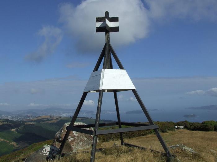
On the ground, the reference point is indicated by a structure in the form of a pyramid of stones, boards or metal tubes. Depending on the purpose, there are several types of benchmarks:
The system of interconnected fundamental and ordinary reference points forms the GGS - the state geodetic network.
On the maps, the reference point is marked with special icons. They are distinguished as follows:
All these points are marked on the real surface of the Earth with metal pyramids or ordinary benchmarks. Geodetic centers indicating the location of the point are applied to maps by coordinates, that is, as accurately as possible, with indications of elevation marks.
What is a reference point? Elevations included in the general geodetic network, mounds, hills or free-standing buildings with spiers, towers or bell towers are designated by conventionally accepted combined icons. GHS points in maps with large scale absolutely everything is indicated. Astronomical points, which are landmarks, are indicated only in cases where they are starting points in a given area.

The installation of permanent signs is carried out by the State Geodetic Leveling Network. The ground parts of the benchmarks are mutually visible to each other at a certain distance. The design and height of signs depend on the purpose, local conditions, soil and distances from one point to another.
Geodetic points can be made in the form of metal or wooden pyramids, stone or reinforced concrete pillars. The height of each structure depends on the binding location. Any benchmark serves as a tripod or support for the measuring instrument and the observer.
The underground part of such a structure is made in the form of a foundation monolith filled with concrete. A mark cast from metal is built into the point itself, which is the center of the point. The inscription on the latter indicates the number and type of this item. The name of the organization that performed the work and the year of installation are cast together with a mark (usually cast iron).

Disc-shaped benchmarks, made by cast iron, are installed in the walls industrial buildings, locks, in the abutments and This is done to monitor the static state of large structures. On disk stamps, in addition to inscriptions, there are protrusions intended for installation. The purpose of geodetic marks can be divided into the following categories:
Fixed points in construction are a guarantee of timely detection of the mobility or instability of a large object, such as a hydroelectric dam or a high-rise building.
Thanks to the interconnected system of designated points, a state geodetic network is formed. Special catalogs contain lists with specified coordinates of all such points. This information is used by topographers to study the surface of the planet, in engineering and geodetic surveys, for various needs of the country's economy.

Lists indicating the values of the coordinates are brought to the officers of the army along with topographic maps. Artillerymen are also well aware that the reference point is a mark indicating a known height, a kind of support for shooting on the ground.
The reference points on the Celsius temperature scale are considered to be the values of boiling and freezing of water at sea level.
In business, this concept is used to describe a certain state of affairs where certain actions can lead either to complete failure or to success.
Since the reference point is a kind of reference indicator, a “hook”, this concept can be used in many areas of human life.
Investigating the causes of frequent stress in people who constantly live in megacities, scientists have found that the unnatural visual environment is to blame. The distribution of right angles and lines, buildings of a uniform color, a large number static objects negatively affects emotional condition person. The psychophysiological direction in science, called visual ecology, claims that the absence hallmarks architectural decorative elements overloads

The eye must highlight, fix some point, detail, element in the visual space, so that the brain perceives the environment as comfortable, close to natural and harmonious. Only then does a person have a feeling of aesthetic and emotional satisfaction.
Benchmarks in business are like airbags. They can be used to increase the competitiveness of the enterprise. If we take as a basis some marketing techniques or the state of affairs in the current period, we can identify comprehensive measures that need to be taken to change the situation for the better.
INSTRUCTIONS AND PROPHECIES OF THE Blessed MOTHER ALIPIA GOLOSEEVSKY, Kyiv...

Eufillin dropper in ampoules is used to treat pathologies that ...

Among all ointments for the treatment and prevention of joint diseases, the most ...