INSTRUCTIONS AND PROPHECIES OF THE Blessed MOTHER ALIPIA GOLOSEEVSKY, Kyiv...


Gone are the days when the connection diagram of electrical appliances, including lamps, was "customized" to the existing switching devices, taking care of optimal location the latter. At present, there is such a variety of switches, switches, and so on, different in functionality and technical capabilities, that you can safely do the wiring in such a way that turning on and off the electrical appliances used is as convenient as possible for their user. A special case is lighting control from two places (points), that is, a pair of switches.
The classic scheme for connecting one lamp (lamp) is known to everyone. You need 1 switch, which is located in the most accessible or convenient place for lighting control: at the beginning or middle of walk-through rooms, long corridors, galleries, alleys (); at the entrance to the room or entrance, and so on. Almost everyone has experienced how inconvenient this can be.
And now the same and other options for controlling lighting devices, but using 2 switches:
As you can see from the examples, 2 switches are not only very convenient, but also save energy, that is, ultimately, money. After all, the light can be turned off immediately, as soon as it is no longer needed. And it does not need to be left all night, as was the case with the 1st switch, for example, in long corridors when returning to their beginning to de-energize the lamps did not make sense. After all, the light was turned on to pass this corridor.
The considered application of two switches assumes that, regardless of the position of the switching contacts of one of them, the other can always turn on or off the lighting at any time. Ordinary switches, which mankind has been using since the invention of electricity, are completely unsuitable for this. After all, they were not initially designed for such work, because in one of their two positions they open (break) the electrical circuit. Therefore, no matter how you connect them together, it doesn’t matter if one of them has open contacts, the second one will never turn on the appliance. And they must be connected somehow to each other, since it is assumed that they will be used to control the operation of the same lamp, that is, they are installed as part of the 1st common electrical circuit.
For independent control of lighting, and other electrical appliances from two places, relatively recently appeared on the market of electrical goods, the so-called walk-through switches are used.
They are also called pass-through switches or toggle switches and switches. And there are also cross switches, but these are slightly different and more complex devices used in conjunction with walk-throughs to control electrical appliances from three or more points. They can be installed instead of walk-throughs, but they will cost more, but on the contrary, they cannot be changed. Externally, from the front side, these switches are no different from ordinary switches. The same body and 1 or 2 keys (sometimes a different type of control part) for switching on and off.
Externally, the pass-through switch differs from a conventional switch in the following: on the back of the case, where they are connected, it has 3 terminals for them. That is, 3 conductors are connected to the pass-through switch. A conventional switch has only 2 terminals (a cross switch has 4). This is if the switching device is single-key.
If you need to control 2 groups of lamps of one lamp, that is, two-gang (double) pass-through switches will be needed, then you need to look for devices with six terminals for the connected wiring. Dual conventional switches have only 3 terminals (cross switches have 8).
And now about the internal constructive and resulting from them differences in work. The circuit supplied to the feed-through switch exits it along 2 lines, between which it switches. That is, in each of its 2 positions, this switch closes one line coming out of it, and breaks the second. It turns out that he, as it were, never breaks the chain passing through him. How this works in practice and provides independent control using 2-way switches by 1 electrical appliance is discussed in the next chapter and can be clearly seen in the diagrams given in it.
There is only one way to connect two pass-through switches for switching the 1st lighting or some other electrical appliance or several connected in series, that is, combined into one group. So it's impossible to go wrong with this. Below is the connection diagram for one lamp.

In this standard scheme it can be seen that the pass-through switches are connected in series one after the other in a circuit break between the consumer of electricity and the phase. Moreover, they must be connected by 2 wires. In the following diagram of two switches per light bulb, you can more clearly see the operation of the entire circuit as a whole.

In the previous figure, the electrical appliance was turned on, and in this one it was turned off by switch No. 2. Obviously, the same action could be done by switch No. 1. And from the current position of the switches, it is clear that any of them can be re-powered electrical appliance.
It is very easy to assemble such a scheme. For switches, in the same way as shown in the figures, the input (common) terminal for phase or zero is located on one side of the case, and 2 output terminals on the other. So feel free to connect them, and in any order, with 2 wires between each other. And then, to the already connected switches, we bring the rest of the wiring: to one of them, to which zero is connected, and to the other - phases. Since all electrical devices should be connected through the junction box, the diagram below is correct assembly the entire chain with its use.

To turn on and off 2 groups of electrical appliances, you will need dual (with two keys) feed-through switches. Next scheme just for such a circuit, assembled using a junction box.

The figure clearly shows and in the comments to it it is signed that pass-through switches of 2 different modifications will be required - one with a phase connection from above, and the other from below. Despite the apparent complexity, this chain is quite simple to make. On the switches, just as shown in the figure, there are marks in the form of arrows that tell you which wire goes where.
Before buying and installing a two-gang switch, you first need to decide what it is for at all? And it is intended to control two lighting circuits from one point.
Do not confuse it with pass-through switches, which play other roles. They differ from each other in the number of contacts. Therefore, when choosing, look first of all not at the front panel, but at the back of the switch.

two-gang light switch

two-gang simple switch
Let's say if you have 2 or more light bulbs in the chandelier, using a two-gang switch, you can make it so that when you press one key, only half of the lamps turn on, and when you press the second, all the rest at once. 
It can also be controlled by two different lamps located at separate points from each other - for example, lighting sconces at different ends of the room or even in another room. 
A two-key switch differs from its one-key counterpart not only in the number of switches, but most importantly, in the number of contacts. There are only 3 of them here. One common and two outgoing. Through them, the phase is separated and then returned to the separate wires again. junction box or goes directly to the fixtures.

Note that you will need at least a three-wire wire to install a double switch, even if you do not have a PE protective earth conductor in your apartment wiring. 
Installation of a two-gang light switch and wire connection
There is nothing complicated in the connection diagram and in the process of installation, installation and connection of wires to the switch contacts. First of all, the switch must be disassembled. To do this, dismantle the keys themselves. If you can’t do it manually, simply by pulling them towards you, use an ordinary screwdriver, prying the keys from the side. 
As a result, you have the body itself with fasteners on the sides and the inner contact part in your hands. The main task is to supply voltage from the phase conductor to the common contact. Further, when two keys are closed, this phase will diverge to one or the other lighting circuit. 
To find the central contact, look at the marking, since it may not always be located exactly alone and in the center. 
But what if you do not understand the inscriptions or they are erased and painted over? Then you need to use a contact screwdriver with a tester with a battery-powered dialing function.
Insert any metal object (stud, screw) into the intended common contact. You wrap your fingers around it, and touch the other two contacts with a screwdriver.
When you alternately press the keys, that is, turn on one - check, then turn off the first and turn on the second - check that the screwdriver LED should light up every time. If this does not happen, then this is not a general contact. 
To connect a common contact, use the conductor phase coming from the junction box gray color. You clean the end of the core, put it between the contact plates and tighten the screw with a screwdriver. 
Next, connect the other two wires in the cable to the outgoing pin connectors. 
The connection of the conductors directly to the two-gang switch itself is now complete. Insert the body into mounting box and tighten the fixing screws. 
Then you tighten the two spacer screws, which help the fastening fork with teeth to rest against the walls of the box as much as possible and firmly hold the switch housing inside it.  After that, you can return to place all the decorative frames and the keys themselves.
Installation of connections of a two-gang switch in a junction box
The following cables can enter the junction box or junction box:

In order not to get confused, follow the following order:
Connect all neutral conductors first. They are usually of blue color. Zero does not pass through two-gang switch and comes directly from the shield to the luminaire, through the connections in the switch box.
All stripped cores can be connected using Wago quick-clamp terminals.  Although everyone has a different attitude towards them, but it is for lighting circuits with minimal loads that they are ideal.
Next in order is protective earth. This is a green/yellow wire. If you don’t have a grounding conductor in your apartment or the lamp body is insulated and the cable is two-core, then, accordingly, this connection will not be in the junction box. 
It remains to connect the phase conductors. Here you need to be extremely careful. First, clamp the phase in the Vago terminal block, which comes from the power supply. Then, in the same terminal, insert the core that comes from the common phase contact of the two-gang switch.
You should have 4 free unconnected wires left. Two of them are the wiring that goes to the chandelier or sconce, and the other two wires are phases connected to the lower outgoing contacts of the two-keyboard.  Take two more clamps and SEPARATELY connect these conductors through them. Thus, you will connect two lighting circuits to the fixtures independently of each other.
Connection on a chandelier or lamp
In a lamp or chandelier, terminal blocks are usually used for connection. Run on them the cores of the cable coming out of the junction box according to the color marking. 
The factory lamp must have wires of exactly the color that are prescribed in the rules. Phase - a gray or dark-colored conductor should go to the central contact of the lamp, and zero - blue to the bulb base itself.
Grounding yellow-green colors can be attached both to the terminal and directly under the screw on the housing. 
Errors when connecting a two-gang switch
The first mistake that an illiterate specialist can make is to put on the switch not a phase, but zero.
Remember: the switch must always break the phase conductor, and in no case zero.
Otherwise, the phase will always be on duty on the base of the chandelier. And an elementary replacement of a light bulb can end very tragically. 
By the way, there is one more nuance because of which even experienced electricians can rack their brains. For example, you wanted to check directly on the contacts of the chandelier - the phase comes there through a switch or zero. Turn off the two-keyboard, touch the contact on the chandelier with a Chinese sensitive indicator - and it glows! Although you have assembled the circuit correctly.
What can be wrong? And the reason lies in the backlight, which are increasingly equipped with switches. 
A small current, even in the off state, still flows through the LED, applying potential to the lamp contacts. 
By the way, this is one of the reasons for the blinking LED lamps off. How to deal with this can be found in the article "". To avoid such an error, you need to use not a Chinese indicator, but a multimeter in voltage measurement mode.
The second error is when the phase supply conductor is connected not to the common contact of the switch, but to one of the outgoing ones. In this case, the circuit will not work as it should. All lights will only light up if you press two keys at the same time. But if you press only the key to which the phase does not come initially, then the chandelier will not light up at all. 
If you entered new apartment, where it was not you who connected the chandelier, and it behaves in such a strange way, that is, it does not react as expected to the two-key switches, then the point is most likely precisely in such an erroneous installation of the supply wires. Feel free to disassemble the switch and check the common contact.

If you have a backlit switch, an indirect sign of such an incorrect connection may be the failure of the neon light bulb. Why indirect? Since here everything depends on which key you will start the phase on.
The third common mistake is to connect the neutral wire on the chandelier not to the common zero in the junction box, but to one of the phase wires.  To avoid this, use and observe the color marking of wires, and even better, if you do not trust the colors, check the voltage supply using a high-quality indicator or multimeter before turning on the lamp.
This article will talk about connecting a light switch in an apartment with one connected lamp. Previously, this was the simplest thing - two wires, we turn on the switch in the gap and that's it. But the times of Khrushchev and panels with the simplest electrical networks have passed in modern houses it's a bit more complicated. In fact, for a person who is more or less knowledgeable in technology, this is a simple matter that requires only: basic knowledge about electricity and the operation of the switch, a flat and Phillips screwdriver, a voltage indicator (optional).
The article is divided into two stages:
The light switch looks like this in the diagram:

This is the simplest circuit. In order for a standard 220V lamp to be switched on, two wires must be connected: live (L) and neutral (N).
When the electrical circuit is not interrupted and an electric potential occurs in the phase wire, current flows through the lamp and the lamp lights up. The light switch has the task of closing or opening an electrical circuit in order to light or extinguish the lamp. In addition, a protective (earth) conductor must be connected to the protective terminal of the lamp in order to equalize the potential of the lamp body with the potential of the earth. This protection against electric shock is needed, for example, when touching the body of a damaged light bulb.
The following scheme is closer to the present:

Here, a 3-wire power cable is supplied to the electrical unit.
Additional cable is routed from electrical box to the lamp. As we have already determined, the light switch has the task of interrupting the circuit in only one place, and this place is the phase wire.
Attention! If you make a mistake and connect the neutral wire to the switch instead of the phase wire (and the phase wires will go directly to the consumer), everything will work - when pressed, the lamp will turn on or off. However, the problem will arise that despite the light bulb being off, the electric potential will be applied to the lamp itself. This creates an additional risk of electric shock if you want to replace the lamp with the lights off - the phase will still be present on the wires and on the lamp. As a result, during any work to replace a burned-out lamp, it will be necessary to turn off the voltage in the home switchgear(open circuit with circuit breakers). In general, it's best to do the right thing.
For the above circuit in the example considered, we will add two more elements that may not be used if there is a circuit breaker, but it is worth mentioning them anyway. These elements are:

This as yet unconnected conductor may be useful in the future, for example, when it is necessary to install a double switch and a lamp with large quantity light bulbs to selectively turn on the light on different levels brightness.
Here is an example of a classic dark gray switch.

There are many holes here, but we will only be interested in the 4 located in the red rectangle. These are equivalent to terminals 1 and 2 in the diagrams above. The other holes in the switch have no function. In addition, there are gray plastic elements for snapping the case in the upper and lower parts.

Returning to the front of the switch, after removing the key (usually with your fingers, pressing slightly towards you), we see a plastic element that is used to attach the key and switch. It is not needed during assembly, so slightly pry it with a flat screwdriver and remove it.


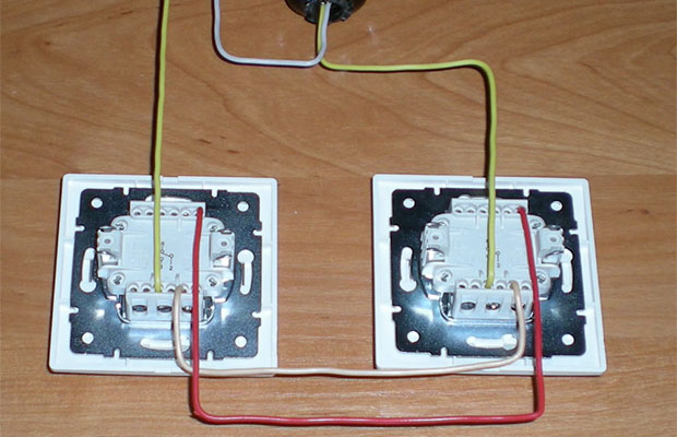
According to the diagram, 3 wires are freed from external insulation: the lower 3-wire harness is power, the upper 4-wire cable is the connection to the lamp, and the 3-wire cable on the right is power to the next switch (you probably won’t have it).

When you assemble or replace circuit breaker, you may have a slightly different wiring diagram:
To make sure that there is no power, use a voltage tester (probe) to check if there is a potential of 220 V on the wires of the power cord.
The next step is to remove the insulation from the ends of the cable. It is better to carry out this operation with an insulation stripper. If you do not have it (most likely not) - take a mounting knife and strip the ends by 20 mm.

After stripping the insulation, connect the neutral wires using the electrical connector.

There was no blue wire in the four-wire cable to the lamp. We will use gray as a neutral. In order to avoid misunderstandings in the future, it is advisable to wrap the end of the cable with the wrong color with electrical tape.

We connect the protective wires in the same way.

The connecting neutral and protective wires are hidden inside the box. AT this case there are three phase wires left that must be connected to the switch.

On one side of the switch we insert a phase wire going to the circuit breaker.

On the other side of the switch is a phase wire that leads to the lamp.

We collect the switch. Lightly tighten the screws alternately so that you can align the switch in the wall evenly. Depending on the manufacturer, the method of fastening and connecting the wires may be different.

Put the key on the mechanism.

Sometimes a plastic decorative casing is put on first, and the key is at the very end.

A socket, a switch and a lamp are the main components of any electrical wiring in an apartment, private house, garage or other office space. Therefore, every prudent homeowner must know how to connect the circuit of all appliances when conducting repair work or the construction of a new structure with their own hands, including combined ones, which are combined in one building.
Not so long ago, connecting the wires from the switch to the electrical circuit alternating current was carried out randomly. Therefore, in houses of old buildings most of such electrical circuit devices still remain connected in violation all safety rules. Naturally, this did not affect the operation of the switch itself, but the safety of operation of such a device remains in great doubt.
Recently, to save wires and wall space, manufacturers electrical appliances began to combine and combine several devices in one case. Wherein most often combine a socket and a key switch as thanks to this connection scheme it is achieved maximum efficiency and ease of use of such electrical appliances.
Today, you can consider several options for how to connect a combined socket and switch. At the same time, quite recently it was difficult to find several electrical appliances of different functionality in one building in an apartment.
Therefore, the connection diagram of the socket and the switch was carried out by connecting the wires in the junction box without combining these devices. Now this option is applicable if for some reason it is not possible to install such consumers one next to the other. Although the separate connection of the socket and switch has its positive aspects.
 But recently, apartments have increasingly begun to use special blocks in which manufacturers have combined electrical outlet and switch. At the same time, the connection diagram of such a device has been greatly simplified. First of all, this is due to the fact that no need to run two separate wires to every consumer. In addition, there are other advantages of such a block:
The only significant drawback of such a combined block is the inability to replace one element, failed - sockets or switches. In most cases you will need complete replacement devices. At the same time, modern blocks are produced with one-key, two-key or three-key switches, combined in one housing with a socket.
by the most simple option how to connect a socket, combined in one housing with a single-gang switch, is to connect all the wires of the mains and devices according to the diagram in the junction box. At the same time, there is a clear sequence for carrying out such work.

Such a system combined in one housing functions quite simply. When the switch is turned on, phase is supplied to the outlet through the switch. Such a scheme is effective, for example, if you need to connect lighting through an extension cord to utility room, and turn it off with single-gang switch.
Modern blocks that combine a socket and a single-key switch in one housing are very popular, while each device will be used separately. To install such an outlet with a light bulb switch, there are a number of simple manipulations.
Thanks to this scheme, the socket, combined in one housing with the switch, will work independently of the switch, which, in turn, will perform its main functions of turning the light bulb on and off.
Basically, blocks that combine a socket and a switch with two keys installed on the partition between the doors to the bathroom and toilet. With the help of only one unit, it becomes possible to control the light in two rooms and connect any consumers of electricity to an AC outlet.

As you can see, the connection diagram of a single-key and two-key switch, combined in one housing with a socket, differs only in the number of wires. In the first case, four wires are used, including ground, and the second option provides for five conductors.
In this article, we will consider the issue in detail. No need to break your head
to whom to contact with this problem, where to get a specialist electrician. There is no need to spend time searching and spending money on a call, all this is done easily and simply. You just need to follow detailed instructions given in this article and the question how to install a light switch, will be solved without any difficulties and puzzles.
So, we have a new one-button switch and the desire to install it.
The installation site looks a little dull so far, an empty socket and two wires sticking out of it, but that's only until we installed a new switch.
First of all, before carrying out all the work, it is necessary, using the voltage indicator (pointer), to determine the wire with the incoming phase. To do this, alternately bring it first to one wire, then to another. We mark the desired one with an insulating tape.

Now, we turn off the electricity, check its absence on the wires, with the help, and only after that we get to work.
There are many different types of switches. They differ: by manufacturers, by price category, quality of workmanship, various methods connecting wires to terminals and so on.
Let's consider two main installation options. In the first case, we will install a switch of a cheap price category up to 80 rubles.
We prepare the switch for installation, and for one thing we will find out how the switch works.

Using a flat screwdriver, remove the switch key, put it on the left or right side and disconnect it from the case.

We unscrew the two screws located diagonally on the protective frame, disconnect it from the mechanism.


There are four screws on the mechanism, two of them are contact screws, they are designed for attaching wires to the mechanism. The other two set in motion the spacer mechanism, which is designed to securely fix the mechanism in the socket.

contact screws.


Screws for the left and right spacers.


We unscrew the contact screws, on the upper end side it will be seen how the pressure plates move.

One of the contacts is incoming, the phase comes to it, the other is outgoing, the phase goes to the lamp from it. Each contact has two holes for connecting wires. We figured out how the switch works, proceed to the next step.
We clean the wires, remove required amount insulation, about 1 cm.

On inexpensive single-gang switches, as a rule, the designation of contacts, incoming and outgoing, is not indicated, but just in case, look at the back wall of the mechanism, the designations can be as follows:
These are the most common designations.
We return to our switch. We insert the stripped wire into the hole, make sure that it is between the clamping plates, tighten the contact screw. We check how well the wire is fixed. It should not swing and stagger, if such a fact takes place, we tighten the contact screw. A poorly stretched contact will burn and eventually lead to failure of the switch.
Do not overdo it, on switches of an inexpensive price category, feints and threads are not very reliable, it is very easy to rip off.

The bare core of the wire should stick out of the contact by 1-2 mm.

Insert and tighten the second wire.

We unscrew the screws of the spacer mechanism, insert the switch into the socket, align it horizontally and fix it. We tighten the spacer screws and check the reliability of fastening the mechanism in the socket.

We install the protective frame, tighten the diagonal screws, securing it to the mechanism.

Installing the key. Before installation, we look at the alignment of the pins and grooves of the moving part of the mechanism and the key.

This completes the connection of the switch.

Consider now the second installation option.
This option includes switches of an expensive price category over 100 rubles apiece.
Preparing the switch for installation. During the process, we look at its device.
These switches are usually not sold in complete set. The mechanism and the key are together, and the frame is separate. This is to allow you to be creative in the design of the switch, such as a white key, a black frame, and so on as you see fit.
The switch key is removed very easily by hand. We're filming.

On the left and right are the screws of the spacer legs.


Flip the switch. The first thing that catches your eye is the complete absence of screw, terminals and clamps. This category switches has plug-in contacts, which are quite well proven in lighting.

Let's take a closer look. On switches of this class there are always symbols.
In this case:
Each contact has two plug-in contact holes.

We clean the wires, remove 1 cm of insulation.


We stick the wires one by one into the contact.

The wire should go tight and rest. In this case, it is allowed that the wire insulation sticks out of the contact by 2-3 mm. We check how the contact is clamped, we try to pull the wire back, if with a certain effort (not with all the force) it is not pulled out, the contact is good. We continue to connect the switch.

Let's move on to the next thread.

If it becomes necessary to pull the wire out of the plug-in terminal and adjust the length of the stripped core, press the lever specially provided for this purpose.

We press and the wire is free again free.

After connecting the wires, we proceed to install the mechanism in the socket.

If your mechanism, without any difficulties, is installed in the existing socket and is securely fixed there, then you just have to put on the frame and install the key. But as a rule, in most cases, the mechanism in the socket is not fixed, the spacer legs do not reach the edges of the socket, it is too large. To How to connect the light switch if such a situation arises? Let's figure it out.The fact is that earlier there were other standards and switch mechanisms were more massive. Now the switches have become more compact, the mechanisms no longer take up so much space in the socket, and the installation of the switch in the socket has undergone some changes.Under new, modern switches, socket boxes are made corresponding to them.

They are now made not from iron, as before, but from special non-combustible plastic.
When purchasing a new switch, you must definitely purchase a socket for it, they basically have a standard diameter of 67 mm.
So, in this article, we have analyzed in detail two connection of a switch with one key, having analyzed two various examples installation, and now, we can rightfully consider this topic closed.
Material
Tool
TOTAL: 650 rubles
INSTRUCTIONS AND PROPHECIES OF THE Blessed MOTHER ALIPIA GOLOSEEVSKY, Kyiv...

Eufillin dropper in ampoules is used to treat pathologies that ...

Among all ointments for the treatment and prevention of joint diseases, the most ...