


"The woman is created for a man, not a man for a woman" - such a postulate ...


Strengthening brick walls. The main methods for amplifying brick walls belongs:
Sealing cracks on the facial surfaces of the walls;
Installation of metal belts;
Installation of unloading beams;
Operation of individual sections of walls;
An increase in their carrying capacity with the help of reinforced and reinforced concrete obligations;
Ensuring spatial rigidity and stability, etc.
With small stabilizing cracks, their seal is made by cement-sandy solution with the addition of 30% of the limestone test. With a significant weakening of the walls, the masonry cementation is carried out by cement -_ polymer or expanding solution.
In the event that the cracks in the wall are through the walls of the walls from both sides on the front at 1/2 brick depth with a mandatory dressing device into one brick every four row of masonry, and in long and wide cracks arrange the castle with an anchor from Rolling profile, which is strengthened with anchor bolts (Fig. 39).
Fig.39. Sealing cracks brick inserts
in a simple castle and with anchor
In places of formation of through cracks to stabilize them from two sides of the walls, steel lining of a strip steel 50 x 10 mm with a fastening of them with bolts on both sides of the wall (Fig. 40, a). Similarly, they come with the appearance of through cracks in the corners of the building (Fig.40, B) and in places of crossing outdoor and inland walls (Fig. 40, B).
Fig.40. Methods for enhancing brick walls
a) installation of steel bonds on bolts; b) in the corner of the building; V - the same in places of conjugates of the outer and inland walls: 1- double-sided metal pad from strip steel; 2 - Round steel diameter
20-24 mm; 3 - the same, with cutting at two ends
With a significant amount of cracks and when the seal does not restore the carrying capacity of the wall, they produce a smoke of individual parts of the walls.
With a strong destruction of brick walls to enhance brick masonry apply one-way or double-sided reinforced concrete walls. When the device of one-sided walls, the enhanced walls are clogged or installed on the solution in the drilled wells anchors, to which the reinforcement grids with a diameter of 8-10 mm with a cell size of 150 x 150 mm are welded (Fig.41, a).
With a double-sided device of reinforced concrete walls in the enhanced wall, through holes are drilled in which metal chucks with washers are installed, to which the same reinforcement grids are welded as the device of one-sided walls. The thickness of the gain wall reaches 100-150 mm (41, b).


Fig.41. Strengthening the brick wall of one-sided (a) or double-sided (b) pavement
a) - one-sided palate: 1 - enhanced wall; 2 - slabs of overlapping; 3 - pavement;
4 - pins with a diameter of 8-10 mm; 5 - reinforcement grid with a diameter of 6-8 mm; b) - double-sided palate: 1 - enhanced wall; 2 - reinforced concrete walls of amplification bound by heavy walls with an enhanced wall; 3 - reinforcement grids welded to the washers of heavy; 4 - heavy with washers skipped through drilled holes in the wall; 5 - holes drilled in the wall for ski pass; 6 - Wall surface prepared for concreting (stripping, notch, flushing)
When there are many cracks on the building facades, they are resorted to eliminate them to ensure the spatial rigidity of the buildings carrier box Using the strapping belt device. The installation of metal belts also produce with the deviation of the walls from the vertical as a result of uneven precipitate (Fig.42).
As metal belts, the steel of a round or square section with a diameter of 20-40 mm is used, which is installed under the overlapping of each floor. Some ends of metal belts weld to trimming the corners, which are installed at the corners of the building, and the second are fixed in the coupling clutches (talp).
For cases of spatial rigidity, the tension of metal belts start simultaneously on all floors to avoid uneven load transmission. When you need to restore the verticality of the wall, the tension of metal belts start from the bottom floor.
The specified value of the tension force is provided by special dynamometric keys in stretch couplings.

Fig.42. Ensuring the spatial rigidity of the building island
1 - heavy; 2 - tension coupling; 3 - metal gasket; 4 - Schweller No. 16-20; 5 - Corner
Strengthening simpleness. Strengthening age can be carried out by:
Increase their cross section;
Blackheads;
Devices metal carcasov;
Reinforced concrete and plaster reinforced fees;
Installation of flexible or rigid cores.
 .
.
Fig.43. Strengthening of sadness of bearing walls:
a, b) - reinforced concrete rope; c) - rolling metal rolling; d) - reinforced concrete core;
e) - the same, metallic; 1 - brick simpleness; 2 - Armature; 3 - concrete; 4 - transverse steel communication;
5 - steel corner; 6 - steel plank; 7 - Armature frame; 8 - steel core
Strengthening brick columns and pilaster. Brick columns and pillars are enhanced similarly to brick stones, i.e., by the device of metal, plastering or reinforced concrete rims (Fig.44).

Fig.44. Strengthening brick columns and pillars using the device
metal frame (a), reinforced concrete (b) or reinforcement (c) clip
1 - brick column; 2 - metal frame or reinforcement fittings; 3 - cement-sandy solution or concrete of deposit
To increase the efficiency of the metal rope, horizontal planks are given pre-voltage using electric heating to temperature 120 0 C.
According to the second method, instead of slats, metal rods are used, the ends of which are welded on one side to vertical corners of the framing of the column, and other ends having a threaded end are passed into the pre-welded sections of the corners or pipes, after which it is created in the rods horizontally with a torque wrench. Voltage and additional column compression (Fig.45).

Fig.45. Strengthening brick columns using prevailing strained rods
1 - corners; 2 - Cancer Cancel; 3 - transverse rod; 4 - nut; 5 - washer; 6 - plaster layer; 7 - straight wedge; 8 - reverse wedge; 9 - rigidity edge; 10 - reference corner
Brick pilasters can enhance with the help of steel or reinforced concrete (Fig.46).

Fig. 46. \u200b\u200bStrengthening pilaster steel (a) or reinforced concrete (b) robes
1 - steel corners; 2 - connecting strips (clamps); 3 - Stubborn washer 10-12 mm; 4 - bolt with a diameter of 18-22 mm; 5 - Zacken cement mortar; 6 - clamp with a diameter of 18-22 mm; 7 - reinforcement grid; 8 - concrete; 9 - Concrete crackers
The reinforced concrete clip is performed from a 12.5 class concrete and above with reinforcing vertical rods and clamps. The distance between the clamps should be no more than 150 mm.
Strengthening brick walls allows you to increase their operational characteristics. Very often you can see cracks in the walls. brick houseWhat points to their weakness and the presence of a bad bearing support. There are various methods for amplifying brick walls, allowing to increase their resistance. About some of them will tell the article.
The basis for strengthening brick walls is their deformation, the causes of which can be:
Evaluation of the degree of damage to the brick walls, by loss of carrier elements, may be:
Weak - up to 15%. Conditioned:
Average - up to 25%. Caused by:
High - up to 50%. It may arise due to:
Tip: Walls that have lost more than 50% of strength should be considered destroyed. The presence of the above damage is the basis to carry out repair and restoration work.
Repair and subsequent strengthening of brick walls, the schemes of it can be very different, but in any case it is necessary:
IN brick houses Cracks can be:


In the scheme:
Walls made of silicate bricks can be strengthened in such ways as:
Choosing a home strengthening method, a large number of factors should be taken into account.
It can be:
The strength of masonry from bricks depends directly from the percentage of reinforcement by its clamps.
With external inspection, you can estimate:
Tip: To restore the strength of the bearing walls of the lady, where there are cracks, it is necessary to accomplish their strengthening.

Eliminate cracks and prevent the emergence of new defects with their own hands, by making the reinforcement of the walls (see).
This uses:
Instructions for strengthening the wall by the reinforcement grid offers:
A wall of silicate brick can be enhanced by a reinforced concrete belt device.
His advantages:
Failure:
When using reinforced concrete robes, such specifications, as:
For the manufacture of a construct from a reinforced concrete "shirt", it is necessary to install the reinforcement grid throughout the perimeter by fixing it without masonry by retainers.
Tip: To strengthen the brick wall, create a shell, which exceeds the strength of the wall itself several times.
The performance of the costume is:
This type of construction part of the load takes over, freeing the masonry.
When making a clip:

The photo shows the construction of the closure of composite raw materials. This is one of the most efficient methods to enhance the walls of the brick, through the use of high-strength fibers: coal and fiberglass.
They allow to increase strength:
Technology of work:
Tip: Talking should be removed after a set of 50% of the strength of the new masonry, the value of which is indicated in the project.
Installation of steel rope significantly increases the carrier capacity of the building.
For its manufacture, you need to purchase:

Tip: When finishing a large area, the process must be performed using a mortar pump.
Traditional methods with the use of composite materials and injections, allowing quickly and efficiently enhance brick walls, can replace innovative methods of process.
Its essence is as follows:
Injecting wall allows you to:
When gaining composite materials:
Strengthening masonry, gaining openings in brick walls must be fulfilled completely to restore absolutely all damaged zones. It is very important to reconstruct the house in a timely manner in order to prevent complete destruction of the walls. Any method, with proper execution, enhances brickwork, increases the stability of the building to the loads acting deformations and other factors. All features of the work shows the video in this article.
When reconstructing residential buildings with brickwork walls, there is a need to restore the carrying capacity or enhanced masonry elements due to an increase in the loads from the pressed floors. With long-term operation of buildings, there are signs of the destruction of commonens, pillars and masonry of walls as a result of uneven sediment of foundations, atmospheric influences, roof leaks, etc.
The process of restoring the supporting ability of masonry should be started with the exception of the main reasons for cracking. If the uneven buildings of the building contributes to this process, this phenomenon should be excluded by the methods known and previously described.
Before acceptance technical solutions For strengthening structures, it is important to estimate the actual strength of carrier elements. This estimate is performed by the method of destructive loads, the actual strength of the brick, the solution, and for the reinforced masonry - the yield strength of the steel. In this case, it is necessary to take into account the factors that reduce the carrying ability of structures. These include cracks, local damage, masonry deviations from vertical, disruption of connections, supporting plates, etc.
As for the enhancement of brickwork, the accumulated experience of reconstruction work allows you to distinguish a number of traditional technologies based on the use: metal and reinforced concrete robes, frames; on the injection of polymer cement and other suspensions in the body of masonry; On the device of monolithic belts along the top of the buildings (in cases of superstructures), pre-strained screeds and other solutions.
In fig. 6.40 The characteristic constructive and technological solutions are given. The presented systems are aimed at comprehensive compression of walls using adjustable tension systems. They are performed open and closed types, with external and internal location, provided by anti-corrosion protection.
Fig. 6.40.Constructive and technological options for amplifying brick walls but- a scheme for amplifying brick walls of the building with metal heavys; b., in, G.- nodes of placement of metal heavyness; d.- scheme for placing a monolithic reinforced concrete belt; e.- The same, heavyweights with centering elements: 1 - metal litter; 2 - Stretch coupling: 3 - monolithic reinforced concrete belt; 4 - slab overlap; 5 - anchor; 6 - centering frame; 7 - Support plate with hinge
To create the desired degree of tension, tight couplings are used, access to which should always be opened. They allow, with the elongation of heavyness as a result of temperature and other deformations to produce additional tension. The compression of elements of brick walls is made in places of the greatest rigidity (angles, interfacing of outer and inner walls) through switchgear plates.
For uniform compression of wall masonry, a special design of a centering frame is used, which has a hinge support for the support and distribution plates. Such a solution provides long-term operation with sufficiently high efficiency.
The location of the heavy and centering frames are closed by various kinds of belts and do not violate general form facade surfaces.
For the elements of walls, simpleness, pillars, having the destruction of brickwork, but not lost stability, a local substitution of masonry is produced. In this case, the brick brand is taken by 1-2 units higher than the existing one.
Working technology provides: a device of temporary unloading systems that perceive the load; Disassembly fragments of broken brickwork; Masonry device. It should be borne in mind that the removal of temporary unloading systems should be carried out after a set of masonry strength of at least 0.7 R. CL . As a rule, such restoration work is carried out while maintaining the structural scheme of the building and actual loads.
Extremely effective receptions for restoring unwritten brickwork, when it is required to preserve the former type of facades. In this case, the brick is very carefully selected on the colors and sizes, as well as the seam material. After restoring the masonry, sandblasting is made, which allows you to obtain updated surfaces, where new plots of masonry are not allocated from the main array.
Due to the fact that the stone structures perceive mainly compressive efforts, the most effective way to enhance them is the device of steel, reinforced concrete and armament subsidies. At the same time, the brickwork in the cable operates in conditions of comprehensive compression, when transverse deformations are significantly reduced and, as a result, the resistance to the longitudinal strength increases.
The estimated effort in the metal belt is determined by the dependence N \u003d0,2R. KJL × l.× b., where R. KJL - estimated resistance of masonry, TC / m 2; l. - length of the plot of the enhanced wall, m; b.- wall thickness, m.
To ensure the normal operation of the brick walls and prevent further disclosure of the cracks, the initial step is to restore the bearing capacity of the foundations by the increase in strengthening, excluding the emergence of uneven sediments.
In fig. 6.41 shows the most common options for strengthening stone pillars and seasplets with steel, reinforced concrete and armo-cement clips.

Fig. 6.41.Strengthening columns with steel rope (A), armofrarkasami (b), grids and reinforced concrete clips ( in, G.) 1 - enhanced design; 2 - enhancement elements; 3 - protective layer; 4 - shield formwork with clamps; 5 - injector; 6 - Material hose
Steel clip consists of longitudinal corners for the entire height of the enhanced design and transverse planks (clamps) from flat or round steel. The step of the clamp is not less than the size of the cross section, but not more than 500 mm. To enable the closure, it is necessary to injected gaps between steel elements and masonry. The monolithic design is achieved by plastering with high-strength cement-sandy solutions with additive plasticizers who contribute to greater adhesion with masonry and metal structures.
For more efficient protection to the steel clip, a metal or polymer mesh is installed, which causes a solution with a thickness of 25-30 mm. With minor scope of work, the solution is manually applied using a plastering tool. Large volumes of work are carried out by the mechanized path with the supply of material with mortar pumps. To obtain a high-strength protective layer, setting and pnegotonization installations are used. Due to the high density of the protective layer and large adhesion with elements of the masonry, a joint work of the design is achieved and its carrying capacity increases.
The reinforced concrete shirt device is carried out by installing reinforcement grids around the perimeter of the enhanced design with fastening it through the locks to the brickwork. The mount is carried out by using anchors or dowels. The reinforced concrete clip is performed from a fine-grained concrete mixture not lower than class B10 with a longitudinal assembly of the A240-A400 classes and transverse - A240. The step of the transverse reinforcement is adopted not more than 15 cm. The thickness of the cable is determined by the calculation and is 4-12 cm. Depending on the thickness of the clip, the production technology of work is significantly changing. For both of the thickness of up to 4 cm, the methods of applying concrete to opprete and pneumatic concrete is used. The final finishing of the surfaces is achieved by the device of the plastering stratum layer.
For clippers up to 12 cm thick along the perimeter of the construction enhanced, the inventory formwork is installed. In its shields, injection tubes are installed through which the fine-grained concrete mixture is injected under a pressure of 0.2-0.6 MPa in the cavity. To increase the adhesive properties and filling the entire space, concrete mixtures are plated by administering superplasticizers in the amount of 1.0-1.2% of the mass of cement. Reducing the viscosity of the mixture and an increase in its permeability is achieved by an additional impact of high-frequency vibration by contacting a vibrator with a shirt formwork. A fairly good effect
gives a pulse mode of supplying the mixture, when short-term exposure of increased pressure provide a higher speed gradient and high permeability.
In fig. 6.41, g. A technological scheme for the production of works by injection of reinforced concrete robes is given. Installing the formwork is made on the entire height of the design with the provision of protective layer of replenishment. The disconnection of concrete is carried out by tiers (3-4 tiers). The process of completing the concrete feed is fixed according to the control holes from the opposite side of the discharge point. For accelerated hardening of concrete, systems of thermoactive formwork, heating wires and other methods of increasing the temperature of the hardening concrete are used. Disassembly of the formwork is carried out on tiers when the concrete of platform is reached. Hardness mode t.\u003d 60 ° С Provides rampant strength for 8-12 hours of warm-up.
Reinforced concrete robes can be performed in the form of non-removable formwork elements (Fig. 6.42). In this case, the outer surfaces may have a small or deep relief or a smooth surface. After installing a non-removable formwork and fastening its elements, the space is provided with the space between the amplified and the enhancement design. The use of a non-removable formwork has a significant technological effect, as it disappears the need for disassembling formwork, and most importantly - the finishing cycle of work is eliminated.

Fig. 6.42.Strengthening columns using formwork cladding from architectural concrete 1 - enhanced design; 2 - Armokarkas; 3 - cladding elements; 4 - Concrete omonication
The most efficient non-removable formworks should be considered thin-walled elements (1.5-2 cm) made from dispersed-reinforced concrete. To engage formwork to work, it is supplied with protruding anchors that significantly increase adhesion with stacked concrete.
The solution of the mortar is different from the reinforced concrete thickness of the applied layer and the composition. As a rule, plaster cement-sand solutions with additive plasticizers that increase physicomechanical characteristics are used to protect the reinforcement grid and ensure its adhesion with brick masonry. The technology of building processes is practically no different from the execution of plaster works.
To ensure the collaboration of the elements of the clip at its length, exceeding 2 or more times, the installation of additional cross-links is needed through the masonry cross section. A amplification of brick masonry can be produced by injection. It is carried out by injection through pre-drilled cement or polymer-cement solutions. As a result, the masonry monolith is achieved and its physicomechanical characteristics increase.
Injection solutions are presented with sufficiently strict requirements. They must have low water separation, low viscosity, high adhesion and sufficient strength characteristics. The solution is injected under pressure to 0.6 MPa, which provides a rather extensive penetration zone. Injection parameters: The location of the injectors, their depth, pressure, the composition of the solution in each case are selected individually, taking into account the fracture of the masonry, the state of the seams and other indicators.
The strength of masonry, enhanced injecting, is estimated by SNIP II-22-81 * "Stone and arm-change structures." Depending on the nature of the defects and the type of injected solution, correction coefficients are established: tC \u003d.1,1 - in the presence of cracks from the force and when using cement and polymer-cement solutions; tK\u003d 1.0 - in the presence of single cracks from uneven sediment or in connection between the combined walls; tC \u003d.1.3 - in the presence of cracks from the power effects in injection of polymer solutions. The strength of solutions should be within 15-25 MPa.
Strengthening brick jumpers is a fairly common phenomenon, which is associated with a decrease in the bearing capacity of the spacer due to the weathelation of seams, adhesion disorders and other reasons.
In fig. 6.43 Constructive embodiments of jumpers using various kinds of metal linings are given. They are installed by punching the stages and holes in the brickwork and are in the future are rocked by cement-sandy solution on the grid.

Fig. 6.43.Examples of amplification of brick wall jumpers but, B.- by teaching overlaid from the corner steel; in, G.- Additional metal jumpers from the schwelller: 1 - brickwork; 2 - cracks; 3 - lining from corners; 4 - strip overlays; 5 - anchor bolts; 6 - schawler's lining
For the redistribution of efforts to reinforced concrete jumpers due to an increase in the overlap loads, metal unloading belts are used, made of two channels and bolted bolted connections.
Strengthening and increasing the stability of brick walls. The gain technology is based on the creation of an additional reinforced concrete shirt with one or two sides of the wall (Fig. 6.44). The production technology of works includes the processes of preparation and cleaning of the walls of the walls, drilling holes for anchors, anchors, installations, attachments to anchors of reinforcement rods or grids, omonority. As a rule, with sufficiently large volumes of work, a mechanized method of applying a cement-sand solution is used: pneumatic concrete or torturing and less frequently manually. It is then a rapid layer is applied to align the surfaces and follow-up operations associated with the wall surface finish.

Fig. 6.44.Strengthening brick walls reinforcement but- individual rods of reinforcement; b.- reinforcement frames; in- reinforcement grid; g.- reinforced concrete pilasters: 1 - enhanced wall; 2 - Anchors; 3 - Armature; 4 - plaster or torcret-concrete layer; 5 - metal trample; 6 - reinforcement grid; 7 - Armokarkas; 8 - concrete; 9 - Opal
An effective admission to the enhancement of brick walls is a device of reinforced concrete single and bilateral racks in the stable and pilaster.
The technology of the device of double-sided reinforced concrete racks provides for the formation of a fine to depth 5-6 cm, drill through holes in the height of the wall, fastening with the help of the injections of the reinforcement frame and the subsequent omnulation of the resulting cavity. For sampling, cement-sand solutions with plasticizing additives are used. The high effect is achieved when using solutions and fine-grained concrete concrete with a preliminary house of cement, sand and superplasticizer. Such mixes other than large adhesion have the property of accelerated hardening and high physical and mechanical characteristics.
When erecting one-way reinforced concrete pilasters, a vertical stable device is required, in the cavities of which anchor devices are installed. The latter is carried out fastening the reinforcement frame. After its placement, the formwork is installed. It is performed from individual plywood shields combined by clamps and attached to the wall with anchors. The fine-grained concrete mixture is injected using pumps that are stuck through the holes in the formwork. Such technology is used in a two-way device pilaster with the difference that the process of attaching the formwork shields is carried out with the help of bolts overlapping the wall thickness.
The need to strengthen building structures in the process of their operation occurs both in the reconstruction and technical re-equipment of the building and due to the physical wear and various injuries caused by corrosion of materials, mechanical effects, the effects of the aggressive environment, poor-quality production of structures and violation of the production of construction and installation work, impaired rules of operation and conditions of production technology.
Restoration and strengthening of stone structures can be performed different wayswhich can be consecrated into three groups: amplification without changing the calculated scheme, with a change in the calculation scheme and with a change in the stress state.
The results of the survey of stone buildings, their designs and elements are summarized in the technical conclusion, in which, on the basis of their technical condition, conclusions are made about the need for their strengthening or recovery.
The most common methods of restoration of stone structures are: plastering, injection of existing cracks, partial or complete elaborating elements.
The restoration of the elements of the plastering is used in surface damage to the masonry in the form of weathering of the solution, defrosting, separation to depth to 150 mm, as well as in the presence of stabilized sediment cracks. The plastering is carried out manually (with the depth of damage to 40 mm) or to the opprete solution of the M75 brand and higher on the basis of cement.
To ensure reliable clutch of the plastering layer with brick masonry, prepare the plastering surface: the masonry is cleaned from damaged bricks and a solution, washed and dried. With a large area and thickness of the plastering layer, the horizontal seams are additionally clearing the horizontal seams at a depth of 10 ... 15 mm, on the masonry there is a notch of the surface, the metal meshes from the wire with a diameter of 2 ... 6 mm or fiberglass are installed. Metal meshs can be performed in place by strapping with a wire with a diameter of 2 ... 3 mm around anchors with a diameter not exceeding the thickness of the seam (Figure 30). The edges of the grids are boating for a damaged area for a length of at least 500 mm. If the damaged area is near corner building, the grid is raised by an angle on the wall at least 1000 mm.
To restore and enhance the stone masonry, which has through-cutting fractures of a force and sedimentary nature (with stabilized precipitation), injection with cement and polymeric solutions is used by injection under pressure to 0.6 MPa using injection devices.
Figure 30 - Restoration of brick walls: A - using wire strapping, b - using ready-made grids: 1 - Anchor, 2 - wire, 3 - Grid, 4 - nails, 5 - recoverable masonry, 6 - solution
The calculated resistance of the stone masonry, enhanced by injection of the solution of cracks, is taken taking into account the correction coefficientm.k.depending on the type of solution and the nature of cracks:
m. k.\u003d 1.1 - for masonry with cracks from the power influences injected by cement mortar;
m. k.\u003d 1.3 - the same, polymer solution;
m. k.\u003d 1.0 - for masonry with cracks from uneven precipitation or disruption between individual elements, injected cement or polymeric solutions.
Partial (full) bobbing is performed if available large number Small, single deep and through cracks with stabilized building precipitation. For the shock, the brick and the brand solution is used, not lower than the brick brand and the solution of the closed masonry. When the sections are smoothed, the adopted rebirth of the seams should be saved (Figure 31).

Figure 31 - Recovery of stone masonry by partial smoke: A - partial terminal on one side, b - the same on both sides: 1 - crack, 2 - restored wall, 3 - partial eclip
To restore the integrity of brick walls, having through-cracks of a force and sedimentary character, a circular steel brackets are used with a diameter of at least 6 mm, the ends of which are fixed in the arranged holes in the masonry to the depth of 100 mm and more, as well as lining or profile metal, fixed In enhanced areas of walls with tie bolts (Figure 32). Staples and lining can be placed with one (with a wall thickness of 640 mm and less) or two sides (with a greater thickness) of the enhanced section, on the surface, in horizontal seams (for the bracket with a diameter that does not exceed the thickness of the seam) and in pre-prepared strangers. Placement of overlays in the stages effectively by offsets of sections of walls, separated crack, relative to each other vertically.
Rolling profiles in the form of channels are applied as lining
No. 16 ... 20, corners with a width of a shelf adjacent to the wall, 75 ... 100 mm, as well as strip steel 70 mm wide and more. Scialing bolts are performed from round steel with a diameter of 16 ... 22 mm. Distance from crack to
the bolts closest to it should be at least 600 mm. In the event that the crack is near the corner of the building, the linings are becoming at an angle of at least 1000 mm. After mounting the pads of the stages are filled with concrete. Steel lining, installed on the surface of the walls without a device, coated with anti-corrosion compositions or plastered on the grid.

Figure 32 - Strengthening walls by adjustments: A - General type of amplification, B -
strengthening simpleness, in - strengthening near the corner of the building: 1 - steel pad, 2
Tie bolt, 3 - nut, 4 - Strain, 5 - support plate (band), 6 -
corner, 7 - crack
If it is impossible to achieve the required degree of strength to increase without increasing cross-section of the element, the gain methods that increase the cross-sectional area are used by the extension device or bypass.
Building may be stone, arm-change or reinforced concrete.
For extension, a brick and a solution of brands are applied not lower than the actual conventional brand of bricks and a solution obtained by testing samples from the enhanced structure.
Building arrange with a thickness of 1/2 bricks or more. A collaboration with brickwork enhanced design is provided by the device of the furrow in the enhanced masonry depth of 1/2 of the brick or with the help of anchors scored in the seams. For building buildings, the use of longitudinal and transverse reinforcement is possible.
The calculation of the strength of stone structures reinforced by stone (arm-variance) buildings is made according to its collaboration with a strengthened design by introducing an additional coefficient of working conditions to the calculated resistance of the stone wrecker, equal to:
when enhancing the element under load exceeding 70% calculated,
γ k. , aD = 0,8.
when enhancing the element under load not exceeding 70%
estimatedγ k. , aD = 1.
For a device of extension from reinforced concrete, a class concrete is not lower than C12 / 15. The reinforced concrete part is erected in pre-prepared niches or existing brickwork channels (Figure 33). The percentage of reinforced concrete part of the section should be 0.5 ... 1.5%. Since the deformativity of the stone masonry is significantly higher than the deformativity of the reinforced concrete, then when under load, additional concrete and fittings work together with the construction enhanced and reach their calculated resistance in the limit state.

Figure 33 - Strengthening of transplexes with pilasters with monolithic reinforced concrete elements: A, B - through wall punching; B, M - Deletion Device on the one hand: 1 - enhanced masonry, 2 - longitudinal fittings, 3 - transverse fittings, 4 - Concrete gain
An effective method for increasing the strength of stone masonry at small eccentricity is a clockwork: steel, reinforced concrete and mortar.
The most massive elements enhanced by the rope are pillars and simpleness. Poles, as a rule, have a rectangular cross-sectional shape with a ratio of the parties of not more than 1.5, which contributes to effective work by robes that limit the transverse deformations in the section. Sleeple have an elongated form in terms of form, usually with the aspect ratio of more than two. At the same time, additional relationships are established for efficient use in the form of tighter bolts or anchors. The permissible distances between connections (anchors, clamps) are not more than 1000 mm and no more than two thickness of the wall in length, in height - not more than 750 mm. Communications securely fix in enhanced masonry.
Steel clip is a system of longitudinal elements of the corner profile (Figure 34) installed on the solution at the corners or protractions of the structure and the transverse elements (slats) welded to them
strip or reinforcement steel, as well as support linings (when the entire column or seinior is strengthened, when part of the effort from the over-based structures is transmitted to the longitudinal elements). Step shapes take no longer smaller cross-section and no more than 500 mm.
To increase the efficiency of strengthening, transverse strips are recommended to strain. For this, from the side of two opposite faces to the longitudinal elements, the planks only welcome from one end. After that, the slats are heated to 100 ... 120 ° C and weld a second free end to vertical corners in the heated state. When cooled to the slats, the enhanced design is compressed.

Figure 34 - Strengthening of stone structures with steel rope: 1 - amplified construction, 2 - corner, 3 - Planck, 4 - cross-link, 5 - strip, 6 - anchors, 7 - bolt, 8 - reference corner, 9 - steel plate
The reinforced concrete clip (Figure 35) is a spatial reinforcement frame of longitudinal and transverse reinforcement, color-based concrete. This type of closure is applied when
significant masonry damage and can significantly increase the strength of the enhanced stone element.
The thickness of the closure and the cross-sectional area of \u200b\u200bthe reinforcement is determined by the calculation. Approximately the thickness of the clip is taken by 40 ... 120 mm, the diameter of the transverse rods is 4 ... 10 mm. To ensure the clutch with concrete, the longitudinal fittings will be from the enhanced masonry at least 30 mm. The step of the clamps is taken according to the calculation, but not more than 150 mm. Stroke of longitudinal reinforcement - 250 ... 300 mm. For the clip, it is recommended to apply C12 / 15 classes and above.
To increase the contact area of \u200b\u200bthe masonry with the elements of the clot enhancement, it is recommended in the masonry every 3-4 rows to perform grooves to a 1/2 brick depth or clear the laying seams by 10 ... 15 mm in depth. Concretion is carried out by injection, the bent mixture through the injection holes in the formwork, injecting or consecutive concreting with formwork.

Figure 35 - Strengthening of the reinforced concrete rope: a - pillars, b - commonness: 1 - enhanced design, 2 - longitudinal fittings, 3 - transverse fittings, 4 - concrete, 5 - additional transverse connections, 6 - longitudinal fittings, 7 - Anchors
The reinforced solution is carried out by analogy with reinforced concrete, but instead of concrete, a solution of the brand is not below the M50. The mortar clip allows to preserve the existing cross-sectional dimensions of almost unchanged. During the work of work, the formwork does not apply. The cement solution applied by a thin layer of about 30 ... 40 mm performs the communication functions between the enhanced masonry and reinforcement and protect the reinforcement from corrosion. The minimum thickness of the protective layer is: for inner dry rooms - 15 mm, for exterior and wet rooms - 20 ... 25 mm.
To enhance stone structures under the load, exceeding 70..80% of the calculated, effectively (allow you to increase the strength of stone structures by 2-3 times) the use of pre-stressed struts installed from one or both sides of the structure in which the working elements are vertical branches. Runs, and transverse strips perform the role of connecting elements that reduce the free length of the branches.
Pre-stressed struts (similar to strengthening reinforced concrete structures) Consist from corner profiles located in the corners of the structure and connected with each other spacecaps from strip steel or rod fittings. From above and the bottom of the strut transmit the load on the support corners. Pre-voltage of struts is carried out by their inflection in the middle of the length or with the help of jacks.
Calculation of stone structures, reinforced by robes, is made in accordance with.
To restore the integrity of the walls in the pairing places apply steel tightening(Figure 36), shponki.(Figure 37), flexible communications in the form of anchors(Figure 38), as well as crosschakedamaged areas.
Steel tighteningperform from round steel with a diameter of 20 ... 25 mm with threads at the ends and distribution pads from the corners or chambers. Steel tightening are usually in the level of overlapping. The tightening device is produced in the following sequence: arrange a horizontal penabile in a longitudinal wall to a depth of 60 ... 130 mm, drill holes for heavy. In the transverse walls at a distance of at least 1000 mm, the hole is punched to install the camshaft. Heavy fixes on camshafts and pre-strain the screws on the ends in combination with heavy heating. After mounting the tightenings, the tights are covered with anti-corrosion compositions, and the stages are filled with concrete or closed with bricks.

Figure 36 - Restoration of wall pairs with steel fuels: 1
Longitudinal wall, 2 - transverse wall, 3 - overlapping, 4 - chips, 5 -
distribution gaskets, 6 - nuts, 7 - cement mortar

Figure 37 - Restoration of conjugation of reinforced concrete knings: A - with vertical reinforcement frames, B - the same, with horizontal frames

Figure 38 - Restoration of mating flexible connections: 1 - longitudinal Wall, 2- reinforced concrete column, 3 - mortgage part of the column, 4 - welding, 5 - Anchor
To restore wall pairing, swords are also used: reinforced concrete and steel. No more than 2-3 knaps are installed on the floor. For the first floor: in the floor level at the foundation, in the middle of the wall and in the level of overlapping.
Reinforced concrete swords consist of a reinforcement frame from rods
16 ... 20 mm and concrete class C12 / 15 and higher.
Steel swords are performed from plates, corners, chalkers. With the device of steel knaps, vertical stages of 400 ... 600 mm are pierced. Installation of the knaps are produced on solutions of increased strength. The swords are wrapped with a metal mesh, and after installation, they are tightened with a bolt with a diameter of at least 16 mm and plastered with a solution.
The operating of the walls of the walls, is carried out in cases of significant deviations from vertical, shifts, distortions, releasing,
when the deviation from the initial position is more than 1/3 of thickness, with a mandatory fastening of flexible connections to nearby designs: walls, columns, overlaps and coatings.
As a result of uneven precipitation bases of foundations, various stiffness Elements and multi-loading of walls, as well as on the influences of natural and technogenic factors, there is a violation of the spatial rigidity of the building of the building as a whole or of it.
To restore the integrity of the core of the building, belts are used, which perceive uneven deformations, stretching masonry efforts and contribute to the redistribution of the load on the basis.
Depending on the nature of the work carried out (restoration of the stiffness of the operating building, reconstruction or superstructure), steel (flexible, hard), arm-change or reinforced concrete belts are applied causes and types of damage.
Steel flexible strain belts (Figure 39) are a system of horizontal distribution devices consisting of heavy diameters of 20 ... 40 mm, strained with a couplor with double-sided thread (right and left) or twisting nuts at the ends, end and intermediate stops.
There are one or more belts closed contours on the walls.
There is a volume compression of the whole building or its part.
In order to effectively comprise the entire box of the building, the length of most belts is recommended to receive no more than 1.5 short. In high-rise buildings, heavy buildings are installed in the level of overlaps. The connection is allowed with overlaps. In industrial and public
one-storey buildings of heavy buildings are installed in the level of rafter structures.
The belt is installed either on the surface of the walls, worsening the appearance, but reducing the labor intensity of the work, or in the strangers, without changing external view And reliably preventing metal parts from corrosion.
When the belt device in the masonry breaks through horizontal fines of a depth of 70 ... 80 mm and through holes for longitudinal and transverse heavyings. At the corners of the building on solutions of high strength vertically, segments of the corners are installed. If the belts are installed on the surface of the walls, for the convenience of mounting and exclusion of heavy wires in length, intermediate brackets are clogged.
Installation of the belts of the enhanced building is carried out sequentially from the bottom up (Figure 39).
Pre-voltage is performed using connecting couplings with simultaneous tension of all seasures or initially strain the heavy tensioning inside the building, and then the outside. The tension is produced by a torque wrench, a jack or a lombing with a 1500 mm shoulder with an effort at the end of 30 ... 40 kg. To reduce the complexity of tension, it is recommended to carry out electrical or thermal heating. The degree of tension should be controlled by appliances. The seasure is considered strained if they do not sag and when they hit them, the sound of high tone is published. During the device, in conditions of reduced temperatures, their additional tension is performed. After fixing the heavyness and their voltage, the cracks are injected in the walls or a partial crossing is performed depending on the nature and degree of damage.

Figure 39 - Strengthening Building with steel precomprolated belts: 1 - CHAIR, 2 - Coupling with double-sided thread, 3 - Drunk corner, 4 - Schweller pad, 5 - Nut with washer
The calculation of the cross section of flexible heavyness is made from the condition of equal strength of heavy tensile and stone masonry on the cut. Estimated effort is determined by the formula
![]() (16)
(16)
where R.sQ.- the calculated resistance of masonry on the slice, MPa;l.- Wall length; b.-
wall thickness.
Steel rigid belts (Figure 40) are performed from profile steel (mainly from channels, corners and strip steel) and are intended to transmit effort into smaller sections. Belts cover all the building or part of it, are executed closed or unclipped. An unlocked belts are used with the breaks of the building, longitudinal and transverse walls, angles. The profile number is assigned constructively.

Figure 40 - Strengthening part of the building by a pre-stressed steel belt device from rolling profiles: 1 - crack, 2 - Belt from Schweller, 3 - Coupling Bolt, 4 - Nut, 5 - Anchor
Steel hard belts can be previously tense. Tension of rigid belts is carried out using bolted compounds (Figure 41). The diameter of the stretch bolt (studs) is determined by the calculation and approximately 20 ... 25 mm.
Steel rigid belts are installed throughout the contour of the building or its parts in the stranges or on the surface of the walls. Depending on the thickness of the wall, the belt is located with one or two sides of the wall: with a thickness of more than 640 mm - on both sides, with a thickness of less than 640 mm - with one.
The fixation of bilateral belts is carried out by bolts with a diameter of 16 ... 20 mm, which, with the help of nuts, tighten the belts with each other and play the role of anchors. When location of the belt on one side joint
the work is achieved at the expense of the device anchors (Figure 40, option A (in a fine). The pitch of the bolts - 2000 ... 2500 mm, anchors - 500 ... 700 mm.

Figure 41 - Tensioner pre-stressed steel belt from rolling profiles
Steel flexible and rigid belts mounted on the surface of the walls, together with couplings, stubborn corners, lining, are cut and stained or placed on the grid.
With the superstructure of the building in order to increase its spatial rigidity in the level of overlap, the coatings are performed by the armamaton (Figure 42, but)or reinforced concrete (Figure 42, b)belt rigidity.

Figure 42 - Strengthening the walls of the building belts: A - arm-change; b - reinforced concrete: 1 - brick masonry walls, 2 - armamatic belt, 3 - steel mesh, 4 - reinforced concrete belt, 5 - longitudinal fittings, 6 - transverse fittings, 7 - insulation
When the device of the arm-variable belt is allowed to use longitudinal rods of reinforcement in the belt with a diameter of up to 12 mm with thickening of the seam to 25 mm. Approximately the area of \u200b\u200bthe longitudinal reinforcement of the belt in the walls with a thickness of up to 510 mm can be taken within 4.5 cm2 , and with a greater thickness - 6.5 cm2 .
The reinforced concrete belt is performed from the Class concrete not lower than C12 / 15 with reinforcement of the spatial reinforcement frame. It is possible to use tight fittings in the belt. The height of the transverse section of the belt is at least 120 mm, approximately the width of the segment of the belt is taken equal: with a wall thickness up to 510 mm - the thickness of the wall taking into account the insulation, with a thickness of the wall more than 510 mm - the device is smaller in the width of the belt. In place of the device of reinforced concrete belt should include additional insulation of walls for liquidation
"Cold Bridges."
The device for pre-intense reinforced belts is considered in.
Tkachev Sergey
The survey of stone and arm-varia designs is carried out taking into account the requirements of SNIP 11-22-81 "Stone and Armocatament Designs", as well as "recommendations for strengthening the stone structures of buildings and structures."
Before examination stone structures It is necessary to identify their structure by selecting the bearing elements. It is especially important to take into account the real sizes of carrier elements, the calculation scheme, to estimate the values \u200b\u200bof deformations and destruction, identify the conditions of support on the stone construction of beams, plates and other bending elements, the state of the reinforcement (in arm-variables) and mortgage parts. From the above conditions directly depend on the size and nature of defects, the presence of typical destruction (chips and cracks).
For definitions of strength Masonry apply tools and mechanical instruments, as well as ultrasonic devices. Hammets and chisels, by a number of shocks, you can approximately estimate the qualitative condition of the material of stone and concrete structures. More accurate data is obtained using special hammers, i.e. mechanical action devices based on estimating traces or impact results on the surface of the test design. The easiest, albeit less accurate tool of this type - the hammer of Fiztele. At the shock end, the hammer is pressed a ball of a certain size. By elbow shock, creating approximately the same force among different people, a trail-hole remains on the surface under study. The magnitude of its diameter with. using the calibration table estimate the strength of the material .
A more accurate instrument is the Kashkarov hammer, when using the blowing force with a ball according to the material under study, take into account the size of the trace on a special rod located behind the ball.
But the most modern and accurate mechanical appliances are spring: the device of the Academy of Municipal Economy of the RSFSR, the Central Research Institute for Construction Designs. The principle of operation of these devices is based on the accounting of a certain strength of the blow caused by the descent of the springs. The device of this type is a housing in which the spiral spring is placed, connected to the drum rod. After pressing, the spring is released on the trigger hook, and the drum rod is hit. In the tight apparatus device, you can install 12.5 or 50 kg / cm 2 For stone materials of different strength.
To determine the bends and deformations of vertical surfaces, their shape and the nature of the retreats from vertical and plane use a level with a special nozzle that allows you to travel, starting with 0.5 M. Instead of a minimum 3.5 m, when there is no nozzle.
The relief of vertical surfaces detect the method of visiting the tool from one of its rack parking, applied horizontally to the predetermined points of the surveyed surface. Results of measuring the deformations of horizontal or vertical surfaces are applied to the schemes on which it is detected for clarity, like horizontals, lines of equal deviations from horizontal or vertical Planes. The cross section is given to 2-5 mm depending on the degree of deviation or disturbance of the position or local defects of the examined element and its total size.
However, first of all, it is necessary to find out the nature of negative changes in the masonry and establish whether the process of formation of cracks stabilized, or their number and width of the disclosure increase in time. To do this, in the masonry are installed lighthouses.The lighthouse is a strip of plaster, glass or metal that covers both sides of the crack. Lighthouses from plaster and glass in case of continuing deformation that caused the appearance of cracks, burst.
| Devices for diagnosing material strength: A - Fiztele hammer; B - Cashkarova; V - Gun Tinning: 1-calibrated ball; 2 - angular scale; 3. -
Target table; 4-remedy rod for fixing the trace of impact |
|
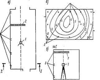 |
Measuring the deformations of the vertical surface using a level with an optical nozzle: a plan; The surface of the wall; B - cut; 1 - Levelier; 2 - Rake; 3 - Places of Applying Peic; 4 - lines of equal deviations from the plane |
 |
Lighthouses for observation of the state of cracks: / -trene; 2-plaster and alabaster solution; 3- Wall material; 4- Light gypsum; 5 - glass lighthouse; 6 - metal plate; 7 - risks in 2-3 mm; 8 - nail |
By measuring the size of the separation of halves of the lighthouse, the nature of the crack change or its stabilization is established. The metal lighthouse is attached to one side of the crack, and it can move along its other edge, on the other side of it, where the initial and subsequent positions of the end of the lighthouse are fixed. The simplest lighthouse is paper beacon, which is a strip of paper glued to a crack, with further crack expansion, a paper beacon is broken.
Cracks in bearing stone structures correspond to stages of cracking (or stages of masonry under compression). With effort in masonry F.
no effort F CRC.
In which cracks appear in the masonry, the design is sufficient to perceive the existing load carrying ability, cracks are not formed. With loads F.  F CRC.
The process of formation of cracks begins. Since the masonry is badly resisting stretching, on stretched surfaces (sections) of cracks
F CRC.
The process of formation of cracks begins. Since the masonry is badly resisting stretching, on stretched surfaces (sections) of cracks
There are much earlier than possible destruction of the design.
As the main reasons for the formation of cracks overlaps:
1) Low quality masonry (bad mortar stitches, non-compliance with the dressing, stouting with violation of technology, etc.);
2) insufficient strength of brick and mortar (fracturing and curvilinery of bricks, non-compliance with drying technology during its manufacture; high mobility of the solution, etc.);
3) sharing in masonry of heterogeneous strength and deformatimity of stone materials (for example, clay brick together with silicate or slag blocks);
4) using the stone materials are not for its intended purpose (for example, silicate brick in conditions of high humidity);
5) Low quality of work performed in winter time (use of not peeled bricks; applying a mortal solution, the absence of antiorrosal additives in a solution);
6) non-fulfillment of temperature and shuffling seams or an unacceptable long distance between them;
7) aggressive effects of the outer environment (acid, alkaline salt impact; alternate freezing and thawing, moisturizing and drying);
8) uneven sediment of the foundation in the building.
It is not by chance of raising foundations indicated last The condition for the occurrence of cracks in masonry. It should be borne in mind that during the mass construction in the stone masonry, solutions were used without contamination additives, skinny, non-albeit, i.e. Very cheap. All this contributed to abundant education. shocked
cracks that need to be separated from purely during the examination sediment
Cracks having a specific, easily determined.
Consider the process of formation of cracks in a masonry in compression
The first stage - The appearance of the first hair Cracked in separate stones. An effort F CRC.
in which cracks appear at this stage depends mainly on the view of the solution used in the masonry:
- in masonry on cement mortar F CRC \u003d (0.8 - 0.6) F U; ;
- in masonry on a complex solution F CRC \u003d (0.7 - 0.5) F U;
- in masonry on lime solution F Crc \u003d (0.6 - 0.4) F U,
where F U.—
Destroying effort.
Second stage - germination and combining individual cracks. This stage begins and intensively proceeds through the southern facade of the building experiencing the highest temperature fluctuations in the atmospheric medium. In addition, germination of cracks is observed with the wrong organization of external drainage, violation of their system in places of periodic wetting of masonry.
Third stage - Further formation of large destruction surfaces and exhaustion of masonry strength.
 |
 |
|
The photo contains a facility with an attic based on the inner transverse wall. On the free part of the roof, a bias was created under the organizational system of the outer drain, but the angle of the building is significantly missed. The arrow shows on a developing crack, which appeared after one year of operation of the reconstructed structure |
Defects of brick masonry and their reasons: a-wear from 20 to 40%; B-wear 41-60%; Overloaded simpleness with wear up to 40%; g - the same, with greater wear; d - exposure of brickwork when wearing plaster |
Analyzing the crack pattern, it should be remembered that the appearance of individual cracks in the dressing stones indicates a surge in a stone cloth. Development of cracks in the second stage Indicates significant overvoltage of the masonry and the need for its unloading or amplification.
In the formation of large destruction surfaces, it is advisable to replacing masonry to a new or its strengthening with a design that fully perceives the operational load.
In the course of operation of the structure, cracks may be revealed due to the illegally large length of the temperature unit or due to the lack of a temperature and shrinking seam. During the reconstruction period with the construction of erkers, hanging elevators, an additional device and mansard Floors Cracks may appear in the masonry due to the insufficient area of \u200b\u200bsupporting the jumpers on the wall and the low strength of the masonry, from the overload of the simpleness and the low strength of the masonry. Other reasons for cracking are possible. For example, randomly arranged cracks often arise in the facilities that were in close proximity to the scene of the pile, or in old buildings, which reaches 40% of the brickwork.
Strength brick and stones It is necessary to determine in accordance with the requirements of GOST 8462-85, solo - GOST 5802-86 or CH 290-74. The density and humidity of the stone masonments are defined in the Creativity with GOST 6427-75, 12730.2-78 by establishing the weight difference of the samples before and after drying. Frost resistance of stone materials and solutions, as well as their water absorption is set according to GOST 7025-78.
Sampling for testing samples are made from low-loaded elements of structures under the condition of identity of the materials used in these sections. Samples of bricks or stones should be whole without cracks. From stones incorrect form cut cubes with a rib size from 40 to 200 mM.or drill cylinders (core) diameter from 40 to 150 mM.. For tests of solutions, Cubes are made with a rib from 20 to 40 mM.composed of two plates of the descendant gluable solution. Samples are tested using standard laboratory equipment. Sections of brick (stone) masonry, from which test samples were taken, must be fully restored to provide the original design.
As mentioned above, the brick buildings of residential buildings of mass series had high reliability and a significant margin of safety. But long term Operation, violations technical Conditions The contents could cause significant damage to carrying brick walls. Depending on the visible damage and state of structures, the loads acting on them, other factors that make it difficult to normal operation, during the reconstruction of activities recovery The bearing ability of brickwork. In addition, with an increase in the storeinations of the structure or an increase in the construction volume of the construction, there is a need for strengthening Brick structures.
Restorationcarrier ability masonry It comes down to the sealing and localization of cracks. Naturally, the specified task must be addressed after identifying and eliminating reasons that caused cracking:
1) eliminate or stabilize uneven rates of foundation by enhancing the foundations or grounds;
2) change the conditions for transmitting the load on the cracked commonness in order to redistribute the load on the large area;
3) to redistribute the load on other (or even additional) structures in the event of insufficient strength of the masonry itself.
It should be noted that the sealing of cracks must accompany both events for Strengthening brick structureswhich are needed with increasing loads and the impossibility of their redistribution on other elements of the structure.
Technologically sealing cracks in brick walls can be made in one of the following methods or by their combination.
Injection of cracks -inspection into cracks of damaged masonry of solutions of liquid cement or polymer-cement mortar, bitumen, resin. This method of restoring the carrying capacity of masonry is applied depending on the type of construction, the nature of its further use, the available injection capabilities, and most importantly, with a local character and a small crack disclosure. It can be carried out using different materials. Depending on their type distinguish silication, bitumenization, resinlation and cement. Injection allows not only to deposit the masonry, but also to restore, but in some cases and increase its carrying capacity, which is happening without increasing the transverse dimensions of the structure.
Cement and polymer cement solutions are most widely used. To ensure the effectiveness of injection, portland cement of a brand of at least 400 with a grinding fineness of at least 2400 cm 2 / g, with a thickness of the cement dough 22 - 25%, as well as the Slagoportland cement 400 brand with a slight viscosity in the diluted solutions. Sand for solution Apply fine with a 1.0 - 1.5 size module or thin-fat with a grinding fineness of 2000-2200 cM 2 / g. To increase the plasticity of the composition in the solution, plasticizing additives are added in the form of sodium nitrite (5% of the mass of cement), polyvinyl acetate PVA emulsion with a polymer-cement ratio P / C \u003d 0.6 or naphthaleneformaldehyde additive in an amount of 0.1% of cement mass .
Injection solutions show sufficiently strict requirements: low water supply, the required viscosity, the required compressive strength and adhesion, a slight shrinkage, high frost resistance.
For small cracks in masonry (up to 1, 5 mm) Apply polymer solutions based on epoxy resin (epoxy ED-20
(or ED-16) - 100 wt.h.; MOGF-9 modifier - 30 wt.ch.; Phap hardener - 15 wt.ch.;thin Sand - 50 wt.h),as well as cement-sand solutions with the addition of thin-headed sand (cement - 1 wt.ch.;superplasticizer naphthaleneformaldehyde - 0.1 wt.h.; sand - 0.25 wt.h.; Water-cement ratio - 0.6).
For more considerable disclosure of cracks Cement-polymer solutions of composition 1: 0.15: 0.3 (cement; PVA polymer; sand) or 1: 0.05: 0.3 (cement: plasticizer sodium nitrite: sand), in / c \u003d 0.6 , Sand size module M K \u003d 1. The solution is injected under pressure to 0.6 MPa. The density of filling cracks is determined in 28 days after injection.
The solution is injected through injectors with a diameter of 20-25 mm. They are installed in specially drilled holes 0.8-1.5 meters along the length of the crack. The diameter of the holes should ensure the installation of the injector tube on the cement solution. Depth of the holes - no more 100 mmThe injector tube is fixed in the holes of the cocointed panels.
 Injecting cracks with a width of up to 10 mm cement-sandy solution:
1- masonry; 2 crack; 3-holes for injectors after 800-1500 mm; 4-steel injector tube; 5-panel, cocked by glue; 6- supply of solution
Installation of reinforcement brackets
used in the methods of restoring the supporting ability of masonry when the cracks disclosure more 10 mm. To do this, in the masonry cutter makes a deepening in size of the bracket. The bracket is fixed by bolts along the edges, the crack itself is usually injected with cement-sandy solution and is condensed with a rigid solution.
Installation of reinforcement brackets: 1-enhanced wall; 2-crack in the wall injectable by cement-sandy solution after installing the bracket; 3-staples made of reinforcement steel; 4-groove in the masonry selected by the cutter; 5-recesses at the ends of the groove performed by the drill; 6-filling cement-sandy grooves and recesses
For significant damagemasonch Network cracksstaples are performed double-sided in this case, the laying is experiencing bilateral compression.The development of numerous cross-cutting cracks can be stopped using instead of a bracket strip steel linings which are installed in 1,5-2 wall thicknesses.
|
|
|
|
|
|
|
|
|
Double-sided reinforcement staples on bolts: 1- masonry; 2- end-to-end crack; 3- strip steel overlays; 4-tie bolts; 5- holes in the wall |
||
Destruction can be as significant that in some cases a partial disassembly is required and a separation of the destroyed brickwork. As a rule, this is done with the device inserts of brick locks equipped with anchor .
 |
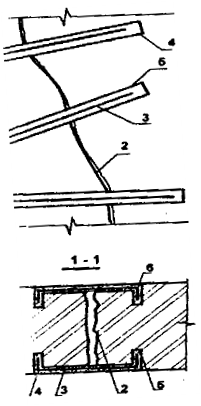
Wide, more 10 mm,crack ( 1 ) intercepts one- or double-sided lining ( 2) , not already from strip steel, but from rolling metal, which is attached to the wall anchor bolts. In this case, the lining is called anchor. The damaged brick on the thickness of two bricks is extracted along the entire length of the crack of the crack and is replaced by the reinforced masonry on cement-sandy solution, called brick castle (3-4
).
|
 |
Partial or complete filling of masonry opening: 1- amplified simpleness; 2-window openings; 3-reinforced masonry made of M75-100 brickwork on a M50-75 solution; 4- seams, crushed by metal plate and condensed with cement-sandy solution |
 |
Schemes for unloading bricks: 1 -Trumbr / CKA-, 2-boards 50-60 mm; 3 racks diameter more than 20 cm; 4-Holded wedges; 5- temporary mounting racks |
Increasing the bearing capacity and sustainability of common people can be provided an increase in the cross section
, Device of various obiam
or metal carcass.
Enhance the cross section Sleeping achieve an increase in its width. In this case, on the two sides of the seal lay out new plots of masonry, which is reliably tied with old, and, if necessary, reinforced. Damaged carrier spots are unloaded, the area of \u200b\u200bthe severity cross sections increases, the area of \u200b\u200bwindow openings is reduced accordingly, so window blocks to be replaced.
When painted on a strengthened common stropile design or the deviation of the wall from the vertical on the value of more than 1/3 of the brick thickness, the stench is pre-unloaded by summing up temporary wooden or metal columns on plaster solutions.
Basic ways strengthening brick masonry,
are well proven device methods obiam, extensions
or shirts
divided by reinforced concrete
and dissolved
. When strengthening reinforced concrete clips, shirts and extensions Concrete class B10 and class A1 fittings, the transverse reinforcement step is not more accepted 15 cm. The thickness of the clip is determined by the calculation and varies in the range from 4
before 12 cm.
Massage clips, shirts and extension, also referred to as plaster, differ from reinforced concrete In the fact that they use a cement solution of the brand 75-100, which protects the reinforcement fittings.
Device of reinforced concrete clip Effectively with surface destruction of the material of transplexes and pillars to a small depth or in the occurrence of deep cracks, when it is possible to broaden the commonness. In the first case, the destroyed seventeensions are cleared to the depth of no less thickness of the reinforced concrete rope, and the cross section of the simpleness as a result of its device does not change. In the second case, the severity cross section increases due to the device of the reinforced concrete rope.
The technological process of the device of the reinforced concrete rope of transplexes consists of removing window fillings, clearing the destroyed sections or cutting down the simplest depth, the removal of window quarters, the installation of fittings, formwork devices, concreting, concrete care, the removal of formwork and disassembly of the disassembly. The working fittings of the reinforced concrete clip can be pre-tense to 100-150 ° C (for example, heating electric shock).
 |
Device of reinforced concrete rims: and - without increasing the cross section of the simpleness; B - with increasing section sensule |
 |
|
 |
The device of plastering pre-stressed court: 1-enhanced wall; 2-metal plates with hardening holes; 3-heavy bonds; 4-holes in the wall for heavy; 5-reinforcement rods welded to plates and pairs of depressed; 6-plaster from cement-sandy solution; 7-reinforcement grids tied to rods |
Instead reinforcement carcasov When enhanced it is possible to use wire meshes with a diameter 4-6 mmwith cell 150x150 mm.In both cases, reinforcement and mesh, and the frames are attached to the strengthened surface with pins (anchors).
On the large squares Additional clamps are installed - no more 1mwith medium length 75 cm.
The formwork of reinforced concrete clip is increasing upwards in the process of concreting. For a device of reinforced concrete rims, the method of the opprete method is used, in which the formwork is not required. In this case, a concrete mixture is applied to the contaminated surface of the seal with a cement-gun. The advantage of this method of the device of the reinforced concrete rope is the mechanization of the concreting process. Reinforced concrete clip increases the carrying capacity of the element in 2-zraza
 |
|
|
Clamps-reinforced concrete clip: 1- amplified surface of the wall; 2-reinforcement with a diameter of 10 mm; 3-clamp bonds with a diameter of 10 mm; 4-holes in the masonry; 5-concrete clip; 6 - reinforcement frames |
|
 |
 |
| Device plastering or reinforced concrete shirt: 1-enhanced simpleness; 2rs; 3-shirt plaster 30-40 mm or reinforced concrete thickness of 60-100 mm; 4-armature with a diameter of 10 mm; 5-reinforcement with a diameter of 12 mm; 6-metal pins | Device of reinforced concrete core: 1-enhanced simpleness; 2-ways; 3-rack (core) from reinforced concrete;
4-niche, cut out in the seaspless; 5-reinforced carcass; 6-concrete |
Mixed shirts and buildings
differ from both by one constructive sign - they are executed one-sided. The shirt can be completed and not all the width of the simpleness - in the form core.
Sometimes steel cubs of brickwork enhancement on constantly exploited buildings leave without protective coating with a solution or concrete, arranging metal carcass
Strengthening.
 |
 |
| Strengthening the seasplets with a metal frame: a narrow simpleness; B-wide simpleness;1-ripic element; 2-steel corners; 3-strap; 4-cross-link |
|
 |
The device of overhead belts from the corners: 1-enhanced simpleness; 2-corners of overhead belts; 3 transverse strips; 4-tie bolts; 5-plaster cement-sandy solution for metal grid |
The device of the metallic frame of semen is less laborious and material consumption than the device of the reinforced concrete clip, and is widely used.
Preparations for the device of metal frames of transplexes consists of unloading of seals, removing fillings of window openings and firing of quarters. At the same time, the method in the corners of the seasplets is installed on all their height and tightly adjusted to the robes of the rack from the angle steel, which after 30-50 cm in height are connected to the bandage steel, welded to the shelves of the angle of jack. Then the rustle is tightened with a wire metal mesh and shuffled.
Metal frame can be applied on the rustle or pour into it flush. In the second case, before installing the frame, the angles of simplets are cut down and horizontal trunks are punched in places of installation of metal connecting strips.
After installing the frame of the gap between the metal elements and the simpleness is thoroughly condensed with a solution. If the destruction and jumpers leafling on the sacrifice have been destroyed, more efficient becomes the strengthening of the rockets from the corners. In this case, the racks are performed slightly longer than the distance between the jumper and the floor. At the top they are attached to the bare reinforcement of the jumpers, and at the bottom to the overhead belt from the channel, mounted on the case of the reconstructed object. The racks are straightened by pairs of clamps, thus the pre-voltage is created. Hidden, dorms, cuts in the shelves of the corners are brewed.
Gain corners buildings are also advisable to produce with overlays from Schawellerlena 1.5-3 m. The lining can be placed both from the outer and from the inner surface of the wall. With brick masonry, they are connected using a tie bolt installed in pre-drilled holes. Coupling bolts are located in the height of the enhanced part of the masonry through 0.8-1.5 m.
|
|
Summing up the racks from the corners: 1-enhanced simpleness; 2-ways; 3-racks from non-equivalent corners, deposited to the side; 4-lines of donuma; 5 mortgage detail; 6-bare fittings; 7-welding; 8-Solution |
|
|
|
In the event of local deformations and to prevent further disclosure, cracks are carried out by increasing conjugation zones longitudinal and transverse walls of the building unloading beams . Pazload beams are installed in previously punched stages from one or two sides of the wall at the level of the foundation or jumpers of the first floor.
Bilateral beams through 2-2.5 M.connected by bolts diameter l6-20 mmdrought through previously drilled holes in beams and wall. One-sided beams are installed on anchor bolts, the smooth ends of which are fixed in the wall of the installation on cement mortar in the previously drilled nests. Connections of beams on bolts are fixed with nuts. Pitch anchor bolts 2-2.5 M..
The gaps between the shelves of beams and brick masonry are carefully condensed with cement mortar of 1: 3. For the manufacture of discharge beams use a channel or boutique No. 20-27. In the locations of the walls of the walls on the cracks on each floor it is installed by brass-tags made of rolled products long 2 m. Before installing a bracket for it in the wall cut out a bar with such a calculation to install a flush with a brick wall surface. In the wall and in the screed mark, drill bolts holes 20- 22 mM.With the help of which the bracket is fixed to the wall. The distance from the crack to the installation site of the bolt must be at least 70 cm. Before installing a bracket, the screed is wrapped with a wire mesh or wire 1-2 mm. After installing the construction of the crack and the trinket, carefully close the brand mortar M100.
 |
 |
|
Installation of metal linings (frame) during the reinforcement of the building: 1-deformed building; 2 cracks in the walls of the building; 3-overlays of chawls or metal plates; 5-tie bolts; 6-stabes for the installation of plates close in solution; 7-holes in the walls for bolts, after installing the bolts is boosted with a solution |
As a rule, development crackedassociated with non-uniform sedimentation foundationsRequires additional measures not only to increase the carrier's ability of masonry, but the stiffness of the entire structure as a whole. Rough violation of stone masonry technology, unacceptable conditions for the operation of the structure, as in the case of uneven precipitation of foundations, are not only the development of cracks in window and doorways, but also violations of the verticality of the enclosing structures.
In places outdoor walls From the internal building stiffness of the building establish links from metal carcasov or reinforced concrete swords. In this case, they say that the building reinforced.
However, most often, after eliminating the causes of the uneven sediment of the foundation, the building needs tightening the housinggenerally. Perhaps the only way of such tightening is creating strained belts .
 |
 |
 |
 |
The device of external stress belts: 1-stranded building; 2-steel tramors; 3-rolling profile from a corner No. 150; 4-coupling; 5-welded seam; 6 cracks in the walls of the building; 7-Strain in the wall for cement-sandy mortar
It should be emphasized here that the most common mistake of enhancing the body of brick buildings with a rigid structural scheme is the creation vertical hard drive disks (Layout or reduction of window openings, vertical metal framework, etc.), while here is the most important horizontal disk stiffness. The stressful belt, also called "bandage", is taken from reinforcing rods with a diameter 20-40 mmconnected by coupling couplings.
In rare cases, steel hire is used instead of fittings. As a result, an enhancement element is obtained, perceiving both tensile and compressive efforts, called sailing space. The linking of the struts are set at the level of the coating and in the level of inter-floor floors, they can be located both from the outer and the inner side of the structure.
 |
 |
 |
|
| The device of internal stress belts: 1-deformation building; 2-steel heavy nuts; 3-metal plates; 4-coupling; 5-holes in the walls that are closed with a solution after packaging; 6-Cracks in the walls of the building | |
Strengthening between interhesives the residential buildings of the 1-447 series are determined by the presence of short cracks and the fragmentation of the brick stone in the places of the ceiling plates. The main cause of destruction is usually an insufficient area of \u200b\u200boverlapping slab or the absence of a distribution cushion.
The most effective method of gain is the installation technology steel crag and reference ties Under the slab overlap, since, as already noted, the creation of a horizontal disk of stiffness in such types buildings has a prevailing value. However, this is a very expensive and inhibited method, it is possible only with complete reconstruction with the residential resettlement. Therefore, try to execute local Strengthen damaged structures.
Local amplification, depending on the type of floor slabs, with partial or phased reconstruction is carried out by:
—an increase in the area of \u200b\u200bsupporting beams with metal or reinforced concrete racks, the effort from which is transmitted outside the zone of destruction;
- Enlarge the area of \u200b\u200bsupporting the plates by means of a belt fixed in the destruction zone of the masonry;
-Force under the end of the slab overlap of the reinforced concrete pillow.
Longitudinal reinforcement intended for the perception of stretching efforts in the extracently compressed elements (with large eccentricity), in bend and stretched elements, in the amplification of brickwork during reconstruction, it is rare enough, therefore this section does not consider. However, with growth seismic The dangers of some regions of Central Russia due to underground workings and other anthropogenic factors, as well as when laying railway and automotive highways near residential neighborhoods, longitudinal reinforcement is used for lining of thin (up to 51 cm)brick walls of reconstructed buildings.
Mesh reinforcement Plots of masonry significantly increases the carrying capacity of the enhanced elements of stone structures (pillars, simpleness and individual sections of the walls). The efficiency of the mesh reinforcement during amplification is determined by the fact that the reinforcement grids stacked in horizontal seams of masonry sections prevent its transverse expansion at longitudinal deformations caused by existing loadsAnd due to this increase the support of the body of masonry as a whole.
Mesh reinforcement is used to enhance masonry from bricks of all kinds, as well as from ceramic stones with slump vertical voids at a row height of no more than 150 mm. Strengthening net reinforcement of masonry from concrete and natural stones with a series of more than 150 mM. little effectively.
For masonry with mesh reinforcement, grade 50 and higher solutions are used. Mesh reinforcement is applied only during flexible or, as well as with eccentricity, located within the cross section core (for rectangular sections E 0<0,33 y). При больших значениях гибкостей и эксцентрицитетов сетчатое армирование не повышает прочности кладки.
For example, It is required to determine the section of longitudinal reinforcement for a brick pillar 51 x 64 cm, 4.5 height m. Pole lays out of ordinary clay brick plastic pressing brand 100
on a brand solution 50
. In the middle section of the pillar there is a given estimated longitudinal force N P.\u003d 25 T.applied with eccentricity e O \u003d.
25 cm In the direction of the section of the section having size 64 cm.
Still reinforcing the longitudinal reinforcement, located in the fired zone outside the masonry. The compressed zone of the cross-section of the pillar is constructively, since during the outdoor army arrangement, a frequent installation of clamps, which prevent pumping compressed fittings, will require an additional PACXode steel. Installation of structural reinforcement in a compressed zone is mandatory, as it is necessary for fastening the clamps.
Cross section area F \u003d 51 x 64 \u003d 3260 cm 2. R \u003d L5 kgf / cm 2 (for F\u003e 0.3 m 2). Estimated resistance of longitudinal reinforcement from steel class A-1.R. a \u003d L900. kgf / cm 2.
Stretched fittings take from four rods with a diameter of 10 mM.F a \u003d 3,14 cm 2.
Determine the height of the compressed section h. at h 0 \u003d 65 cm, E \u003d 58. media B \u003d 51. cm:
1.25-15-51 x (58-65 +) -1900 -3.14-58 \u003d 0,
and from the received square equation Determine x \u003d35 cm<
0.55h o \u003d 36 cm.
Since the condition is satisfied, then carrying the cross section to determine by \u003d 1000:
pr \u003d \u003d 7
hence \u003d 0.94.
Carrying ability of the section
0.94 (1.25 x 15 x 51 x 35-1900 x 3.14) \u003d 25.6 t\u003e n n n \u003d 25 tons.
Thus, with the adopted cross section of the reinforcement, the carrier's ability of the pillar is sufficient.
Complex structures Performed from stone masonry, reinforced with reinforced concrete, working together with masonry. Reinforced concrete recommended at the same time to have masonry from the outside , Which allows you to check the quality of the laid concrete, the mark of which should be taken equal to 100-150.
Complex structures are used in the same cases as laying with longitudinal reinforcement. In addition, it is advisable to apply them, as well as mesh reinforcement, to enhance seriously loaded elements during axial or outcidentren compression with small eccentricity. In this case, complex structures in this case allows dramatically to reduce the size of the cross section of walls and pillars.
Elements reinforced by robes are used to enhance pillars and sizes having a square or rectangular cross-section with a ratio of the sizes of the parties no more than 2.5. The need for such an increase occurs, for example, when adding existing buildings. Sometimes it is required to minimize a masonry having cracks or other defects (insufficient strength of the materials applied, low quality masonry, physical wear, etc.)
Obiam, as well as mesh reinforcement, reduce cross deformations of masonry And due to this increase its carrying relationship. In addition, the hood itself also perceives part of the load.
In the previous sections three types were considered: steel, reinforced concrete and reinforced plaster .
The calculation of the elements from brick masonry, reinforced by robes, with central and outcidentren compression with small eccentricity (not beyond the cross-section nucleus) is made by formulas:
with steel count
N n [(m to r +) f + r a f a];
with reinforced concrete county
N n [(m to R +) f + m b r ode f b + r a f a];
with a reinforced cutting court
N (M R +) F.
The values \u200b\u200bof the coefficients and are accepted:
for central compression=1 and \u003d 1;
with an extracentrous compression (by analogy with high-centranenially compressed elements with mesh reinforcement)
1 - where
N P -reduced longitudinal force; F-masonry cross sections;
F A.-The bottom of the cross-section of the longitudinal corners of the steel cable, installed on the solution, or the longitudinal reinforcement of the reinforced concrete clip;
f b -the cross-sectional area of \u200b\u200bthe closure concrete, concluded between the clamps and masonry (excluding the protective layer);
R a -the calculated resistance of the transverse or longitudinal fittings of the clip;
- the coefficient of longitudinal bending, when determining the value but Accepted as for non-suspended masonry;
t to -coefficient of laying conditions; for masonry without damage t K.\u003d 1; for masonry with cracks t K. =0,7;
t b -coefficient of working conditions of concrete; When transferring the load on the clip from both sides (bottom and top) t B.
\u003d 1; When transferring the load on the clip on one side (bottom or top) t B.\u003d 0.7; without direct load transmission for clip t B. =0,35.
- percentage of reinforcement determined by the formula
x 100
where f X. -Cheatting of a clamp or transverse plank;
h.and b-sizes of the side of the enhanced element;
s-the distance between the axes of transverse slats during steel walls ( hS B, But no more than 50 cm.) Or between the clamps for reinforced concrete and reinforced plasterings (S15 cm).
For example,in the middle section of the sealer size 51x90 cm, Located in the first floor of the building, after the end of the construction of the superstructure will be the estimated longitudinal force N n \u003d 60 t, applied with eccentricity e about = 5 cm, Directed towards the inner edge of the wall. Sleeple is laid out of the silicate brick of the brand 125 on the brand 25 solution. The height of the wall (from the floor level to the nise of the national team reinforced concrete overlap) is 5. m. It is required to check the carrier ability of the simpleness.
Sentennik cross section F \u003d 51 x 90 \u003d 4590 cm 2\u003e 0.3 m 2.
Estimated masonry resistance R \u003d L4 kgf / cm 2. Distance from the center of gravity section to its edge towards the eccentricity
y \u003d \u003d 25.5 cm; \u003d \u003d 0,2<0,33,
eccentricity is within the nucleus of the section. Sleeps look forward to high-centrized compression with a small eccentricity. Elastic characteristic of masonry from silicate brick on a solution of brand 25 - \u003d 750.
Presented flexibility of simpleness NP \u003d\u003d 11.3.
The coefficient of longitudinal bend \u003d 0.85.
The coefficient that takes into account the effect of eccentricity \u003d \u003d 0.83.
We define the carrier ability of the simpleness:
0.85 x 14 x 4590 x 0,83 \u003d 45 200kgf
Since the carrier's ability of the simpleness turned out to be insufficient, then we enhance it with a rocker from steel equilibrium corners with dimensions of 60x60 mm, d \u003d 6 mm. Corners are installed on the solution in the corners of the wall and interconnected by strip steel straps with a cross section 5x35 mm, Welded to the corners at a distance s \u003d 50 cm In the height of simpleness.
Next, determine the carrying ability reinforced Sleepy. Focusing Coefficient t K \u003d 1. Estimated resistance of steel planks R A. =1500 kgf / cm 2. Singing area plank f X. \u003d 0.5х3,5 \u003d 1.75 cm 2. The calculated resistance of the corners of the cage (the load on the corner is not transmitted) R A. =430 kgf / cm 2. Section area of \u200b\u200bcorners F A.\u003d 6.91x4 \u003d 27.6 cm 2. Next, determine the coefficients and , =0,83, =1-=0,61 and the corresponding percentage of reinforcement: \u003d x100 \u003d 0.21%
Hence the carrying capacity of the reinforced simpleness will be:
0,83.085 [(14 + 0.61xx) 4590 + 430 x27,6] \u003d 63800kgf\u003e n n n \u003d 60000 kgf
The carrying capacity of reinforced simpleness is sufficient. 
"The woman is created for a man, not a man for a woman" - such a postulate ...

How is HIV on different time segments manifest? The reasons for the development of AIDS is ...

Stomach Cancer: Symptoms, Causes, Treatment of Stomach Cancer is a change in cell type ...