Preview:To use the preview...


Compressor(from the Latin word compressio - compression) - an energy machine or device for increasing pressure (compression) and moving gaseous substances.
Compressor unit is a combination of compressor, drive and auxiliary equipment(gas cooler, compressed air dryer, etc.).
The generally accepted classification of mechanical compressors according to the principle of operation, the principle of operation is understood as the main feature of the process of increasing pressure, depending on the design of the compressor. According to the principle of operation, all compressors can be divided into two large groups: dynamic and volumetric.
In compressors of the volumetric operating principle, the working process is carried out as a result of changing the volume of the working chamber. Compressor range of this type is varied (more than a dozen types), the main of which are: piston, screw, rotary-gear, membrane, liquid-ring, Roots, scroll, compressor with a rolling rotor.
Rice. 1. Classification of positive displacement compressors
Piston compressors (Fig. 2-3) can be single-acting or double-acting, crosshead And crossheadless , lubricated and without the use of lubrication (dry friction or dry compression); at high compression pressures, plunger ones are also used.
Rotary compressors are machines with a rotating compression element; they are structurally divided into screw, rotary vane, liquid ring, and there are other designs.
Rice. 2.

Rice. 3. : 1 - crankshaft; 2 - connecting rod; 3 - piston; 4 - working cylinder; 5 - cylinder cover; 6 - discharge pipeline; 7 - discharge valve; 8 - air intake; 9 - suction valve; 10 - pipe for supplying cooling water
Rice. 4.
Mainly consists of a working cylinder and a piston; has suction and discharge valves, usually located in the cylinder cover. To impart reciprocating motion to the piston, most piston compressors have a crank mechanism with a crankshaft. Piston compressors are single and multi-cylinder, with vertical, horizontal, V or W-shaped and other cylinder arrangements, single and double acting (when the piston works on both sides), as well as single-stage or multi-stage compression.
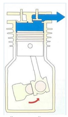
The operation of a single-stage air piston compressor (Fig. 3) is as follows. When the crankshaft 1 rotates, the connecting rod 2 connected to it imparts return movements to the piston 3. In this case, in the working cylinder 4, due to an increase in the volume enclosed between the piston bottom and the cylinder cover 5, a vacuum occurs and atmospheric air, having overcome with its pressure the resistance of the spring holding the suction valve 9, it opens it and enters the working cylinder through the air intake (with filter) 8. During the reverse stroke of the piston, the air will be compressed, and then, when its pressure becomes greater than the pressure in the discharge pipe by an amount capable of overcoming the resistance of the spring pressing the discharge valve 7 to the seat, the air opens the latter and enters pipeline 6. When the gas is compressed in the compressor, it the temperature rises significantly.
To prevent spontaneous combustion of the lubricant, compressors are equipped with water (pipe 10 for water supply) or air cooling. In this case, the air compression process will approach isothermal (with a constant temperature), which is theoretically the most profitable. A single-stage compressor, based on the safety and economic conditions of its operation, is advisable to use with a degree of pressure increase during compression up to b = 7 - 8. For large compressions, multi-stage compressors are used, in which, alternating compression with intermediate cooling, it is possible to obtain gas at very high pressures - above 10 Mn/m2. Reciprocating compressors typically have automatic capacity control based on compressed gas flow to ensure constant discharge pressure. There are several ways of regulation. The simplest of them is regulation by changing the shaft rotation speed.
Operating principles of rotary and piston compressors are basically similar and differ only in that in a piston all processes occur in the same place (working cylinder), but in different time(which is why it was necessary to provide valves), and in a rotary compressor suction and discharge are carried out simultaneously, but in different places, separated by the rotor plates. Other designs of rotary compressor are known, including screw ones, with two rotors in the form of screws. To remove air in order to create a vacuum in any space, rotary liquid ring vacuum pumps are used. The performance of a rotary compressor is usually regulated by changing the rotor speed.
Rotary compressors have one or more rotors, which can be various designs. Rotary vane compressors have become widespread (Fig. 5), having a rotor 2 with grooves into which plates 3 freely fit; the rotor is located eccentrically in the cylinder of the housing 4. When it rotates clockwise, the spaces limited by the plates, as well as the surfaces of the rotor and cylinder housing, on the left side of the compressor will increase, which will ensure the suction of gas through hole 1. On the right side of the compressor, the volumes of these spaces decrease, the gas contained in them is compressed and then it is supplied from the compressor to the refrigerator 5 or directly to the discharge pipeline. The housing of the rotary compressor is cooled by water, for the supply and discharge of which pipes 6 and 7 are provided. The degree of pressure increase in one stage of a vane rotary compressor is usually from 3 to 6.

Rice. 5. : 1 - hole for air suction; 2 - rotor; 3 - plate; 4 - body; 5 - refrigerator; 6 and 7 - pipes for drainage and supply of cooling water
The design of the screw block consists of two massive screws and a housing. In this case, the screws are at a certain distance from each other during operation, and this gap is sealed with an oil film. There are no rubbing elements.
Thus, the service life of the screw block is practically unlimited and reaches more than 200-300 thousand hours. Only the screw block bearings are subject to routine replacement.
The design of the vane-rotor unit consists of one rotor, stator and at least eight plates, the mass of which, and therefore the thickness, is limited. The following forces act on the plate during operation: centrifugal and friction/elasticity of the oil film.
Since the oil film normalizes and becomes uniform and sufficient only after several minutes of compressor operation, during starts and stops there is friction of the plates on the stator and, accordingly, increased wear and tear.
The greater the pressure such a block must pump, the greater the pressure difference in adjacent compression chambers, and the greater the centrifugal force must be to prevent the flow of compressed air from a chamber with a higher pressure to a chamber with a lower one. In turn, the greater the centrifugal force, the greater the friction force at the moments of starting and stopping and the thinner the oil film during operation - this is the main reason why this technology has become widespread in the vacuum area (that is, pressure up to 1 bar) and in the area of pressure up to 0.3-0.4 MPa.
Since the oil film between the plates and the stator is only a few microns thick, any dust, especially larger solid particles, act as an abrasive that scratches the stator and causes wear on the plates. This leads to bypasses of compressed air from one compression chamber to another and productivity drops noticeably.
Unlike small vacuum pumps, where vane-rotor technology is widely used, in compressors of high capacity and pressure above 0.5 MPa, over time it will be necessary to change the entire unit assembly, since replacing individual plates is effective only if the stator geometry is restored, and Such large stators cannot be restored (polished).
Manufacturers usually do not provide any data on the service life of the vane-rotor unit, since it very much depends on the air quality and the operating mode of the compressor. For gas compressors pumping gas almost without stopping all year round, the resource can actually reach more than 100 thousand hours because the oil film is uniform and sufficient all the time without stopping.
And in industrial use, where air flow is extremely uneven and the compressor is started and stopped dozens of times a day, most There is no time for a normal oil film inside the block to operate, which causes aggressive wear of the plates. In this case, the block resource is no more than 25 thousand hours.
In compressors with a dynamic operating principle, gas is compressed as a result of supply mechanical energy from the shaft, and further interaction of the working substance with the rotor blades. Depending on the direction of flow and the type of impeller, such compressors are centrifugal (Fig. 6) and axial (Fig. 7).

Rice. 6. : 1 - shaft; 2, 6, 8, 9, 10 and 11 - impellers; 3 and 7 - ring diffusers; 4 - reverse guide channel; 5 - guide vane; 12 and 13 - channels for supplying gas from refrigerators; 14 - channel for gas suction
A centrifugal compressor mainly consists of a housing and a rotor having a shaft 1 with symmetrically located impellers. The centrifugal 6-stage compressor is divided into three sections and equipped with two intermediate coolers, from which gas enters channels 12 and 13. During operation of the centrifugal compressor, the gas particles located between the impeller blades are subject to rotational motion, due to which centrifugal forces act on them . Under the influence of these forces, the gas moves from the axis of the compressor to the periphery of the impeller, undergoes compression and acquires speed. Compression continues in the annular diffuser due to a decrease in gas velocity, that is, the conversion of kinetic energy into potential energy. After this, the gas flows through the return guide channel into another compressor stage, etc.
Obtaining large degrees of gas pressure increase in one stage (more than 25-30, and for industrial compressors - 8-12) is limited mainly by the tensile strength of the impellers, which allow peripheral speeds of up to 280-500 m/sec. An important feature of centrifugal compressors (as well as axial ones) is the dependence of compressed gas pressure, power consumption, and efficiency on its performance. The nature of this relationship for each brand of compressor is reflected in graphs called performance characteristics.
The operation of centrifugal compressors is regulated by different ways, including changing the rotor speed, throttling the gas on the suction side and others.

Rice. 7. : 1 - channel for supplying compressed gas; 2 - body; 3 - channel for gas suction; 4 - rotor; 5 - guide vanes; 6 - working blades
An axial compressor (Fig. 7) has a rotor 4, usually consisting of several rows of working blades 6, rows of guide blades 5 are located on the inner wall of the housing 2, gas suction occurs through channel 3, and discharge through channel 1. One stage of an axial compressor consists of a row working and a number of guide vanes. When an axial compressor operates, the rotating blades exert a force on the gas particles located between them, causing them to compress, as well as move parallel to the axis of the compressor (hence its name) and rotate. A lattice of fixed guide vanes provides mainly a change in the direction of the speed of gas particles, necessary for the effective operation of the next stage. In some designs of axial compressors, an additional increase in pressure occurs between the guide vanes due to a decrease in gas velocity. The pressure increase ratio for one stage of an axial compressor is usually 1.2-1.3, that is, significantly lower than that of centrifugal compressors, but they achieve the highest efficiency of all types of compressors.
The dependence of pressure, power consumption and efficiency on performance for several constant rotor speeds at the same suction gas temperature is presented in the form of performance characteristics. Axial compressors are regulated in the same way as centrifugal ones. Axial compressors are used as part of gas turbine units.
The technical excellence of axial, as well as rotary, centrifugal and piston compressors is assessed by their mechanical efficiency and certain relative parameters showing the extent to which the actual gas compression process approaches the theoretically most advantageous one under given conditions.
Jet compressors are similar in design and principle of operation to jet pumps. These include jet devices for suction or injection of gas or vapor-gas mixture. Jet compressors provide a higher compression ratio than jet pumps. Water vapor is often used as a working medium.
Turbochargers are dynamic machines in which gas compression occurs as a result of the interaction of the flow with a rotating and stationary array of blades.
Other classifications
By purpose, compressors are classified according to the industry for which they are intended (chemical, refrigeration, energy, general purpose, etc.). By type of compressed gas (air, oxygen, chlorine, nitrogen, helium, freon, carbon dioxide, etc.). According to the method of heat removal - with liquid or air cooling.
According to the type of drive motor, they are driven by an electric motor, internal combustion engine, steam or gas turbine. Diesel gas compressors are widely used in remote areas with power supply problems. They are noisy and require ventilation for exhaust gases. Electrically driven compressors are widely used in manufacturing, workshops and garages with constant access to electricity. Such products require electric current, voltage 110-120 Volts (or 230-240 Volts). Depending on the size and purpose, compressors can be stationary or portable. By design, compressors can be single-stage or multi-stage.
According to the final pressure, they are distinguished:
Vacuum compressors, gas blowers are machines that suck gas from a space with a pressure below atmospheric or above. Blowers and gas blowers, like fans, create a gas flow, however, providing the ability to achieve excess pressure from 10 to 100 kPa (0.01-0.1 MPa), in some special designs - up to 200 kPa (0.2 MPa). In suction mode, blowers can create a vacuum, usually 10-50 kPa, and in some cases - up to 90 kPa and work as a low-vacuum vacuum pump;
Compressors low pressure, intended for gas injection at pressure from 0.15 to 1.2 MPa;
Medium pressure compressors - from 1.2 to 10 MPa;
High pressure compressors - from 10 to 100 MPa.
Ultra-high pressure compressors designed to compress gas above 100 MPa.

Rice. 8.
Compressor performance is usually expressed in units of volume of gas compressed per unit of time (m3/min, m3/hour). Productivity is usually calculated using indicators normalized to normal conditions. In this case, the productivity of the inlet and outlet is distinguished; these values are almost equal at a small pressure difference between the inlet and outlet, but with a large difference, for example, in piston compressors, the output productivity can fall by more than 2 times at the same speed compared to input capacity measured at zero pressure difference between inlet and outlet. Compressors are called booster if the pressure of the suction gas significantly exceeds atmospheric pressure.
Mounting is the process of installing the compressor and engine onto a frame. Due to the fact that reciprocating compressors are characterized by uneven shaking, which, in the absence of a suitable foundation or support, results in excessive vibration, the installation must be carried out taking into account a well-designed foundation.
Rarely does any enterprise operate without the use of compressed air. At some enterprises it is used for coating various surfaces, on others to ensure the operation of stamping equipment. A compressor is used to produce compressed air.
What is a compressor? The official definition is as follows: a device designed to compress gases and pump them to consumers is called an air compressor. How does he work? The principle of operation of the device is quite simple: atmospheric air enters a mechanism that compresses it. For this they can be used different methods, they will be discussed below. The mechanism that compresses air determines the design and principles of operation of the compressor. For efficient work equipment must be connected to the electrical network and the air network through which compressed air will be transmitted. The connection diagram for the electric motor is usually indicated in the operating instructions.
On the market industrial equipment There are many offers for the supply of these devices. It can be divided into those that are used in industry and those that are used in everyday life, for example, for inflating car tires. All these devices can operate from different types of drive. An electric air compressor 220 V, as the name implies, operates from an electric power unit with a voltage of 220 V. But, there are also devices that operate on a voltage of 380 V.

Diesel compressor, powered by an internal combustion engine running on diesel fuel. The use of such equipment is quite popular among builders; it is used when there is no possibility of connecting electrically driven installations. Installations running on diesel fuel ensure operation at remote locations construction sites.
Atmospheric air is supplied to the cylinder head in which the pistons are installed. The power plant, in turn, transmits torque to the shaft, which ensures the movement of the pistons in the cylinder. It is there that the air is compressed to the required parameters. After compression, it is sent to the plant's air system. Piston compressors are divided into oil and oil-free. The oil version differs in that for its effective operation, a special oil is poured into it, which reduces the friction force between the rubbing parts and components of the device. This increases its service life.
There are many ways to transfer torque from the engine to the actuator. In the manufacture of compressors, couplings or belt drives are most often used. The device on which the latter type is installed is called a belt compressor.

The listed types of equipment are used in almost all industries; they differ from each other in performance, size and a number of other parameters. But of course, main characteristic is the amount of pressure that the compressor can create.
Air compressors are distinguished by their operating principle; more on this below.
Piston compressors are one of the most common types of this equipment. As noted above, air compression occurs under the action of pistons moving inside the liners. To meet the needs of industry, high-pressure piston compressors are used. They can be powered by either an internal combustion engine or an electric motor. An industrial high pressure compressor produces between 40 and 500 bar. Compressors of this type are characterized by high efficiency and a service life of up to 2000 hours. Piston compressors are produced in both stationary and mobile versions. To move them, a wheeled or tracked chassis is used.

This is a rather complex device; its design includes oil scraper rings, filters for purifying oil and air, control automation, and this means that to maintain this device in working condition, qualified personnel and special tools and devices are required.
The gas is compressed in such a device under the action of a membrane, which performs a reciprocating motion. The membrane is driven by a rod, which is fixed to the crankshaft.
The membrane plate is fixed to the working chamber and thus there is no need to use additional parts, for example, piston rings, sealing devices, etc.
Air compressor membrane type has the following parameters:
A membrane-type belt-driven compressor is distinguished by the fact that the working medium comes into contact only with the membrane and the internal cavities of the chamber. At the same time, it does not come into contact with the atmosphere. This device is used for pumping harmful and toxic substances.

Another advantage of the membrane product is that it does not need to be lubricated, which reduces the risk of contamination of the transported working environment.
A device in which the process of producing compressed air occurs by reducing its volume is called a positive displacement compressor. These include the following types of equipment:
The history of this equipment began in 1934. Screw compressors are distinguished by high reliability, small dimensions, and low metal consumption, which have led to high consumer demand for equipment of this class. The use of this equipment allows you to reduce electrical energy costs by up to 30%. Installations of this type are installed in mobile compressor stations, ships and other refrigeration units.
Screw rotors with cavities are used as a working body. They are installed in a housing that can be disassembled along several planes. It has holes and recesses for installation and bearings. In addition, air suction and discharge chambers are formed in the housing. Pumps of this type are distinguished by their performance.

These products can develop pressure from 8 to 13 atm, while the air flow can be from 220 to 12,400 liters per minute.
Quite often, one unit of such equipment can replace several units of compressors installed in production shops.
When installing and running in industrial operation For such compressors, it is advisable to install a device at the inlet to clean the air from excess moisture. Some manufacturers complete their products with such filters.
Compressors of this class operate on the same principle as piston ones, that is, on displacement. Energy transfer occurs during compression. During suction, the working medium enters the working chamber, and its volume decreases as the rotor moves. This compression leads to an increase in pressure and the escape of compressed air through the pipe.
Compressors of this type can produce pressures up to 0.3 MPa and are called blowers, and those that deliver higher pressures are called compressors.
Devices of this type have the following advantages:
A more stable, balanced stroke ensures the absence of reciprocating motion. The design of this equipment provides the possibility of direct connection to an electric power unit. The weight of a rotary compressor will be lower than a piston compressor with similar characteristics. The design does not provide for the use of valves. That is, the number of parts rubbing against each other decreases.
Compressors in this group are divided into two types - centrifugal and axial. For the first, the air is exposed centrifugal force is thrown towards the outer part of the impeller. This creates a rarefied space on the suction side. Gas constantly enters the working chamber, after passing the wheel, the air is directed to the diffuser (flow rate damping device), where, in fact, its pressure increases.
In axial-type equipment, air moves along the rotor, and compression occurs as a result of changing the speed of its movement between the rotor blades and the guide device.
These compressors can be classified according to the following properties:

Rotary compressors are used in aircraft engines. It is used to pump air into the combustion chamber.
This term refers to the volume of gas that is injected in a certain unit of time. The unit of measurement for productivity is m3 per minute. This parameter can be specified either at the input or at the output, of course, these will be different numbers. The thing is that when pressure changes, volume changes. This characteristic indicates performance at a working environment temperature of 20 degrees Celsius.
Depending on the value of this characteristic, the following groups are distinguished: high productivity (over 100 cubic meters of air per minute), medium (up to 100 cubic meters of air per minute) and low productivity (10 cubic meters).
Dynamic devices have some advantages over piston devices. They are simple in design and operation. They have small overall and weight parameters. Smooth air supply and they do not require additional lubrication. Their installation does not require the manufacture of massive foundations. But, at the same time, their efficiency is somewhat lower than that of piston engines.
These compressors have found their application in many industries. For example, the chemical and oil and gas industries, metallurgy, mining and many other industries. One of the types of dynamic compressors, turbocompressors, is installed in gas pumping pipelines.
Over many years of operation of such equipment, many devices with different characteristics, in particular, modern machines are capable of providing productivity up to 200 m 3 per minute, with a wheel rotation speed of 250 revolutions per second. And all this with small overall and weight parameters.
The process of installing the compressor and power unit on the frame is called aggregation. Due to the fact that piston-type devices have vibration, it is necessary to design and manufacture the foundation taking into account these characteristics.
These devices have found their application where it is necessary to ensure high requirements for air purity. They are installed in medical institutions, pharmaceutical and chemical industry enterprises. To be fair, it must be said that these devices are considered to be the most affordable devices in terms of their cost. These compressors are easy to operate and maintain. This suggests that there is no need for trained personnel, and when installing them on workplace There are no special requirements.
But oil-free compressors have some disadvantages, such as excessive noise that occurs during operation. But, manufacturers were able to solve this problem by installing soundproof casings on these products.

When choosing an oil-free compressor, you need to pay attention to the power of the device, their performance and operating pressure parameters, which are indicated by the devices installed on the compressor. We must not forget about the volume of the receiver. As a rule, containers with a volume of 50 liters are installed in the compressor device.
The most common method of reducing friction that occurs during the operation of various parts and assemblies is their lubrication. This allows you to reduce the load on the product as a whole, in particular on its key part - the engine.
To solve this problem, special compressor oils are used, which can be used in different conditions operation.
Compressors of this type are cheaper to manufacture. Therefore, the cost of such equipment is significantly cheaper than oil-free analogues. But they are more expensive to operate. This is due to the fact that during operation, along with the removal of air from working area, oil is released. By the way, it must be replaced every 2,000–3,000 hours of operation.
Since microparticles of oil are present in compressed air, oil-collecting elements, such as filters, have to be installed in the system. After a certain amount of time, they also need to be replaced, and this complicates maintenance and requires additional costs for purchasing replacement filters.
However, despite the measures taken, it is not possible to completely clean the air passing through the oil compressor. For example, after air treatment on a screw device, its pollution is 3 mg per cubic meter. The purity of air after it has been processed by a piston compressor directly depends on the level of wear of its parts and components.
This has led to the fact that the use of oil compressors is prohibited in certain technological processes.
The normal operation of the compressor primarily depends on the operation of all its components and parts. In particular, intake and exhaust valves. Inside the compressor, where air distribution occurs, a certain number of spools, distributors and valves are installed. The following types of valves are installed in compressors: poppet, plate, spindle, etc.
To ensure that the equipment does not reduce power indicators and does not consume excess power, the valves that are installed in the compressor must be ground in and must not allow air to pass through. When the valves wear out, they must be urgently replaced. Increased air flow can sooner or later lead to a reduction in the life of the equipment.
Delayed valve response leads to knocking noises; knocking indicates wear is occurring. seat. In addition, a knocking sound may indicate that the upper part of it is pinched in the housing.

The quiet operation of the compressor is a kind of indicator of the quality of the settings and, accordingly, the operation of the device as a whole.
Compressor units of various operating principles and purposes are widely used on construction sites and in production. Compressors can be permanently installed on concrete foundations or mobile, that is, mounted on a chassis.
Regular use of compressor equipment is permissible subject to a number of conditions:
Behind installed equipment, appropriate supervision and maintenance must be established. It must be remembered that maintenance and routine maintenance must be carried out by trained personnel. The equipment that is under the supplier's warranty must be serviced by specialists from the appropriate service centers.

In particular, when washing compressor components and parts, only those liquids and compositions recommended by the manufacturer of this equipment should be used. Storage tanks for compressed air must be installed safety valves, drain valve, pressure gauge. In accordance with the requirements of the operational documentation, these tanks (receivers) must undergo routine maintenance and testing. Their results should be recorded in the maintenance log.
When organizing the operation of compressor and related equipment, it is necessary to use guidelines and other regulatory documents, published by control bodies, for example, Rostechnadzor.
What should a consumer consider when choosing an air compressor? Most importantly, he must understand for what purposes the purchased equipment will be used. It should be noted right away that there are separate industries, and technological operations can only be used with compressors operating without oil.
The key parameters of compressor equipment are:
As a rule, these parameters must be determined by engineers - technologists who develop technological processes with the participation of compressor equipment.

For example, air flow can be calculated according to the following scheme:
When selecting equipment, it is necessary to take into account the growing number of compressed air consumers.
To ensure that the air is under constant pressure in compressor systems, control equipment is installed. The simplest system consists of a pressure sensor and a simple adjustment system. It allows you to maintain constant pressure in the receiver. If exceeded given parameters the compressor is switched off, and after the pressure has dropped to a certain minimum, the automation is activated and turns on the compressor. Such, or almost such systems, are installed in almost all compressor installations. Their presence ensures safe operation equipment.
To perform certain tasks that are performed at home or in the garage, use domestic compressors. As a rule, these are small-sized electrically driven piston compressors. The power of this product is 2.2 kW. Such compressors are able to pump air up to 8 atm.
For the most part, they can easily provide a pressure of 10 atm. Receivers with a capacity of up to 100 liters are used to store compressed air.
As a rule, they are used when performing painting work, internal and external.
Compressed air widely used in industry, construction, and also in everyday life. For example, the owner small production where stamping equipment is used, it is impossible to do without compressed air, with the help of which press activation systems operate.
When performing various road construction works, pneumatic jackhammers, spray guns, and screwdrivers are widely used.
For the operation of all these units, air under pressure of at least 5...7 atm is required, which is provided by a wide class of machines called compressors.
Depending on the features of their design, as well as on the principle of operation, the entire variety of compressor units can be reduced to two types: blade and volumetric.
In vane-type compressors, the necessary air pressure is created due to the interaction of the air flow with the blade grids - movable and stationary. Structurally, such compressors are axial, radial-axial and centrifugal.
The diagram of the last type of vane compressor is shown in Fig. 1.
It is used, for example, in air conditioning systems. The rotor 1, eccentrically mounted on the shaft, is equipped with blades 3, which are thrown away from the housing 4 by centrifugal forces arising during rotation. As a result, the cross-sectional area of the working chamber 2 is reduced, which, when constant flow refrigerant provides the necessary increase in its pressure.
Compressor units of the second type – volumetric – are more common. Here overpressure air is created in special chambers. The volume and order of connection of these chambers are constantly changing during one compression cycle, which causes a corresponding change in the operating air pressure. Compressors of this type are divided into rotary and piston.
Due to their positive features - reliability and ease of use, stable performance characteristics, compactness, etc. - piston compressors have become widely used. Users in the most various fields economic activity We are quite satisfied with the versatility and wide technical capabilities of piston compressors.
Piston compressor device shown in Fig. 2. The compressor consists of a cylinder 1, a piston 2, a motor 3 that rotates the drive shaft, an intake valve 4 and a discharge valve 5, a filter 6 and a receiver 7. 
Operating principle of a piston compressor is as follows. A drive shaft rotating from the engine (crank-crank or eccentric design) converts the rotational motion into a reciprocating movement of the piston, which supplies compressed air to the cavity of the receiver.
The extracted external air is purified by a filter, which is also an air dryer for the compressor. The cyclical flow of air into the working cavity of the cylinder is carried out by the synchronous action of the valves: during the reverse stroke of the piston, the inlet valve opens (accordingly, the discharge valve closes), and during the forward stroke, on the contrary, the inlet valve closes and the discharge valve opens.
The compressor receiver allows you to accumulate compressed air, after which it is further transmitted through pipelines for its further use.
A compressor with a receiver allows for more reliable operation of pneumatic devices, since it reduces fluctuations in compressed air pressure and creates the required volume during prolonged operation of such devices.
Piston type compressors are classified into installations:
- single and double action;
— with different layout of the working cylinder: vertical, horizontal, angular;
- with different numbers of working cylinders.
Determined by the power and purpose of the compressor. For example, when the compressor operates for a long time, it is necessary to install an automatic control system for its operation, which includes an air pressure switch for the compressor. This ensures control of compressor performance when the compressed air flow rate changes, which leads to constant operating pressure values.
For example, when the pressure in the receiver decreases, such a compressor turns on, and when the pressure in the receiver increases to the maximum permissible value, it turns off. The presence of a compressor pressure switch, the price of which depends on the drive power and pressure control range, reduces wear on the pistons and accordingly increases the durability of the compressor.
The required volume of the compressor receiver depends on its performance and permissible pressure fluctuations. It is calculated by the formula
V=(Q/8*Δр) (m 3),
Q – required compressor capacity, m 3 /min;
Δр – permissible fluctuation of working pressure of compressed air, at.
Low-capacity piston compressors are manufactured in a mobile version (see Fig. 3), which allows you to quickly move the unit to a new place of use. 
Such compressors can also be driven by an internal combustion engine.
1. Limited, compared to other types, unit performance.
2. Pretty high level vibrations and noise during operation.
3. The need for frequent Maintenance and repairs.
4. The need for thorough air purification.
Long-term and reliable operation of piston compressors is possible only with timely and high-quality maintenance. In particular, repair of piston compressors is required in the following cases:
— in case of a decrease in unit performance;
— with increased (against the rated values) heating of the compressor unit;
— when oil leaks from the crankcase;
- in case of spontaneous pressure drop;
— in case of depressurization of the pneumatic relay;
— with mechanical knocks in the working cavity of the cylinder;
- with increased carbon deposits on the working parts of the compressor.
What is a compressor? – by its design, it is a machine designed to compress and transport gases with an increase in pressure by a ratio of more than 1.1. Nowadays, the scope and operation of piston compressors is very wide; they are necessary in all enterprises where compressed air is used as an energy source. The compressor can be found in factories, gas filling stations, car services, medical institutions and even shoe repair shops.
Today, the most common types of devices are piston and screw compressors. Since screw compressors have a higher cost, small enterprises, including service stations, widely use piston compressors. Consumers of compressed air in car service centers include pneumatic impact wrenches, pneumatic drills, spray guns, tire changing machines, vacuum oil extraction installations, etc.
The main element of the piston compressor device is compressor head(piston unit). Its design resembles an internal combustion engine. It consists of a cylinder, piston, compressor piston rings, connecting rod, crankshaft, as well as intake and discharge valves. Unlike an internal combustion engine, the valves in a compressor are a plate with a spring and, when a piston compressor is operating, they are not forced into action, but by a pressure difference. To lubricate the piston compressor device, in particular the rubbing parts, oil is poured into the compressor head.
If it is necessary to obtain compressed air of high purity and without oil impurities (for example, in medical institutions), oil-free compressors are used. In such a piston compressor device, the rings are made with polymer materials, and for reliable operation of the piston compressor, graphite lubricant is used.
To achieve higher performance of a reciprocating compressor, compressor heads are manufactured with multiple cylinders, which can be in-line, V-shaped or opposed.
The crankshaft is driven by an electric motor, which ensures the operation of a piston compressor. Depending on the method of connection to the electric motor, piston compressors are distinguished with belt drive and direct drive.

To others important element in the design and operation of a piston compressor is receiver, which is a steel container and is designed to maintain constant pressure and uniform air flow. The receiver also has a pressure relief valve installed if its permissible value is exceeded.
To ensure the operation of the piston compressor in automatic mode, the piston compressor device contains pressure switch(pressure switch), which, when a given pressure is reached, opens the contacts and stops the engine, and when the pressure drops below a certain value, closes the contacts and starts the compressor.
The operation of a piston compressor is carried out according to the following principle: when the piston moves downward, a vacuum is created in the cylinder, as a result of which the intake valve opens. Since the pressure in the cylinder is below atmospheric, air enters through the valve. To clean the incoming air, filters are used in the piston compressor device. During the upward movement of the piston during operation of a reciprocating compressor, both valves are closed. When air is compressed, the pressure in the cylinder increases and the discharge valve opens, through which air enters the receiver. Piston compressors operating on this principle are called single-stage.

One of the disadvantages of piston devices single stage compressors is the limited operating pressure. Operation of a piston compressor of this type is possible with a pressure increase only up to 10 atmospheres. This is explained by the fact that at high pressures the temperature in the cylinder increases greatly and the oil that is used to lubricate the parts can ignite.
To achieve higher pressures in the operation of piston compressors, they use multi-stage principle in which the air is alternately compressed in each stage to a certain value, after which it is cooled in the refrigerator and fed into the cylinder of the next stage, where it is compressed to a higher pressure. Used as a refrigerator in a piston compressor device copper tube with cooling fins.
The operation of reciprocating compressors in small plants is most often based on a two-stage installation with two cylinders. The first stage cylinder, as a rule, has a larger diameter than the second.

When choosing a piston compressor, you must first take into account the characteristics of compressed air consumers. After all, the operation of a piston compressor should not be constant. At correct selection compressor head and receiver, the compressor operating time should be equal to the rest time.
It is worth considering that all manufacturers indicate on their compressors the capacity in l/min only at the inlet. Since productivity decreases with increasing discharge pressure, in order to find out its output value you need to subtract 30% from the indicated data.

Internship assignment in Germany 1. Determine a topic that is relevant to you (or...

The Law “On Education in the Russian Federation”, which was adopted in 2012 and...