INSTRUCTIONS AND PROPHECIES OF THE Blessed MOTHER ALIPIA GOLOSEEVSKY, Kyiv...


Smoke aspiration fire detectors (IPDA) are detectors of a new generation that can provide fire protection of objects at the highest possible level and under almost any operating conditions.
Unlike point and linear aspiration smoke detectors, there are no regulatory restrictions on the maximum sensitivity level, and their principle of operation and design features allow you to effectively protect the most complex objects. For example, areas with high airflow rates, overhead and underfloor spaces with extremely high or low temperatures, dusty and explosive areas, rooms with limited access, rooms with high ceilings, domes, beams, etc. Concealed installation of pipes in overhead space, in building structures or in decorative elements rooms with transparent capillary tubes for the formation of remote air sampling points.
Aspirating smoke detectors were invented by Xtralis over 30 years ago and have been on the Russian market for over 20 years. Until 2009, aspiration detectors were used according to the recommendations of VNIIPO, which were developed for aspiration detectors of each specific type. In 2009, the requirements for the installation of smoke aspiration detectors were defined in the Code of Rules SP 5.13130.2009 fire protection. Fire alarm and fire extinguishing installations are automatic. Norms and rules of design». In the same year, GOST R 53325-2009 “Fire fighting equipment. Technical means fire automatics. General technical requirements. Test Methods”, which for the first time defined the technical requirements and methodology for testing IPDA. These norms and requirements were further developed in subsequent versions of these documents: in GOST R 53325-2012 and in SP 5.13130.2009 with Amendments No. 1.
Of greatest practical interest are class A laser smoke detectors, which have now achieved a fantastic sensitivity of 0.0002%/m (0.00001 dB/m). High-sensitivity laser aspiration detectors provide the highest level of fire protection in cleanrooms, containment areas, operating rooms, computer magnetic resonance, positron emission tomography, pressure chambers, high rooms and areas with air currents: atriums, data centers , in the control room, in industrial shops, in high-rise warehouses, etc. Highly sensitive laser IPDA provide ultra-early detection fire hazard, which determines the minimum material losses, the absence of the need for evacuation and interruption of the enterprise. To ensure the possibility of prompt response of personnel, several pre-alarm and alarm signals are generated at various levels of smoke. Aspiration detectors with increased sensitivity of class B and class C with standard sensitivity, i.e. with the sensitivity of a point smoke detector, have a narrower scope.
Operating principle
According to GOST R 53325-2012, an aspiration fire detector is an “automatic fire detector that provides sampling through a system of pipes with air sampling holes and delivery of air samples (aspiration) from the protected room (zone) to a device for detecting a sign of fire (smoke, changes chemical composition environment)" (Fig. 1). This principle of construction of the detector, unusual at first glance, with pipes with air intake holes and an aspirator, determines a lot of advantages compared to smoke point and linear detectors. Air samples from the controlled room enter the pipes due to the discharge created by the aspirator, which, together with the optical density meter, is located in the processing unit.
The principle of forced air intake (aspiration) from various parts of the room for constant monitoring has become the basis for the creation of a whole line of highly sensitive smoke detectors of the LASD (Laser Aspirating Smoke Detector) series. Effective indoors up to 2 thousand square meters, with a ceiling height of up to 21m, with a length of air ducts - from 50 to 120m.
Each model is equipped with a system for detecting malfunctions in the functioning of the hardware and the air sampling pipe system. With a simple connection to a PC or PPC, standard settings can be changed using the PipeIQ® software, which also handles the design of ductwork and installation of basic equipment.
Functional features of LASD detectors
The air flow from the protected room passes through a chamber with a laser emitter capable of detecting the presence of smoke particles. The laser beam is not reflected from the walls of the chamber, which eliminates background noise and erroneous operation, and the presence of programmable states "ATTENTION", "WARNING", "FIRE" guarantees very early information about changes in the composition of air masses, which in turn prevents the development of critical situations ( stoppage of production, evacuation, material damage).
The highest level of protection for objects, especially those that do not allow the installation of classic point detectors, can be achieved due to the design and principle of operation of the LASD series detectors:
Sensitivity - maximum 0.03% / m;
Log of fixing critical situations - up to 18,000 events;
The influence of the movement of air flows on the reliability of the data is minimized;
Two levels of filtration, FLU2;
Intuitive indication on the front panel;
Maintenance and installation - simple, comfortable and fast;
Minimum costs for the modernization of substation systems.
The LASD System Sensor series is represented by 4 basic models with structural differences.
One laser detector in one channel, up to 1000 sq.m. controlled area;
Two laser detectors in one channel, up to 1000 sq.m. controlled area;
One laser detector in each of two channels, up to 2000 sq.m. controlled area;
Alarm loops (inputs)
Depending on the type of connected detectors, when programming the configurations of Signal-10 blocks ver.1.10 and higher; "Signal-20P" ver.3.00 and higher; "Signal-20M" ver.2.00 and higher; "S2000-4" ver.3.50 and higher inputs can be assigned one of the following types:
Type 1 - Fire smoke double threshold
Fire smoke or any other normally open detectors are included in the alarm loop. The unit can feed the detectors via a loop.
Possible AL modes (states):
In general, when using smoke detectors powered by an alarm loop, the “Fire input re-request blocking” parameter must be disabled. When the detector is triggered, the device generates an information message "Sensor triggered" and re-requests the status of the alarm loop: resets (turns off) the power supply of the alarm loop for 3 seconds. After a delay equal to the value of the "Input analysis delay after reset" parameter, the device starts to evaluate the AL state. If within 55 seconds the detector is triggered repeatedly, the alarm loop switches to the "Fire1" mode. If the detector does not trigger again within 55 seconds, the alarm loop will return to the "On Arm" state. From the "Fire 1" mode, the AL can switch to the "Fire 2" mode in the cases described above.
The "Fire input re-request blocking" parameter is used if the detector is powered from a separate source. According to this scheme, detectors with a large current consumption are usually connected (linear, some types of flame and CO detectors). If the "Block fire input re-request" parameter is enabled, when the detector is triggered, the device generates an informational message "Sensor triggered" and immediately switches the alarm loop to the "Attention" mode. From the "Attention" mode, the AL can switch to the "Fire 1" mode in the cases described above.
Type 2. Fire combined one-threshold
Fire smoke (normally open) and heat (normally closed) detectors are included in the alarm loop. Possible AL modes (states):
When a heat detector is triggered, the unit switches to the "Attention" mode. When a smoke detector is triggered, the unit generates an informational message "Sensor triggered". When the parameter "Locking the re-request after input”, the block re-requests the AL status (for details, see type 1). If the smoke detector operation is confirmed, the alarm loop switches to the "Fire 1" mode, otherwise it returns to the "On protection" mode. From the "Fire 1" mode, the AL can switch to the "Fire 2" mode in the cases described above. When the parameter “Request blocking after input” the device immediately switches the alarm loop to the “Attention” mode. From the "Attention" mode, the AL can switch to the "Fire 1" mode in the cases described above.
Type 3. Fire thermal two-threshold
Fire thermal or any other normally closed detectors are included in the alarm loop. Possible AL modes (states):
Type 16 - Fire manual.
Non-address manual (normally closed and normally open) fire detectors are included in the loop. Possible AL modes (states):
When manual fire detectors are triggered, the unit immediately generates the "Fire2" event, through which the "S2000M" remote control can send a control command to fire automatics systems.
For each loop, in addition to the type, you can configure additional parameters such as:
The maximum length of alarm loops is limited only by the resistance of the wires (no more than 100 ohms). The number of detectors included in one loop is calculated by the formula: N = Im / i, where: N - the number of detectors in the loop; Im – maximum load current: Im = 3 mA for AL types 1, 3, 16, Im = 1.2 mA for AL type 2; i – current consumed by the detector in standby mode, [mA]. The principles of connecting detectors are described in more detail in the OM of the respective units.
The use of these detectors ensures their full electrical and information compatibility with the units in accordance with the requirements of GOST R 53325-2012.
exits
Each BPC has relay outputs. Using the relay outputs of the devices, it is possible to control various executive devices, as well as to transmit notifications to the monitoring station. The tactics of operation of any relay output can be programmed, as well as the activation binding (from a specific input or from a group of inputs).
When organizing a fire alarm system, the following relay operation algorithms can be used:
Control panel "Signal-20M" in offline mode
"Signal-20M" can be used to protect small objects (for example, small offices, private houses, shops, small warehouses, industrial premises, etc.).
The front panel buttons can be used to control the inputs and outputs. Access to the buttons is restricted using PIN codes or Touch Memory keys (256 user passwords are supported). User permissions (each PIN-code or key) can be flexibly configured - allow full control, or allow only re-arming. Any user can manage an arbitrary number of loops, for each loop the powers of taking and taking off can also be configured individually. Similarly, the outputs are controlled using the "Start" and "Stop" buttons. Manual control will take place in accordance with the programs specified in the device configuration.
Twenty alarm loops of the "Signal-20M" device provide sufficient localization of the alarm notification at the mentioned objects when any fire detector in the loop is triggered.
The device has:
Block-modular PPKUP based on the S2000M console and BOD with non-addressed loops
As mentioned above, when building a block-modular PPKUP, the S2000M console performs the functions of indicating the states and events of the system; organization of interaction between the components of PPKUP (management of display units, expansion of the number of outputs, docking with SPI); manual control of inputs and outputs of controlled blocks. It is possible to connect threshold fire detectors of various types to each of the BPCs. The inputs of each of the devices are freely configurable, i.e. for any input, you can set types 1, 2, 3 and 16, assign other configuration parameters individually for each loop. Each device has relay outputs that can be used to control various actuators (for example, light and sound annunciators), as well as transmit an alarm signal to the fire monitoring notification transmission system. For the same purposes, you can use the S2000-KPB control-start blocks (with controlled outputs) and the S2000-SP1 signal-start blocks (with relay outputs). In addition, the system has S2000-BI isp.02 and S2000-BKI display units, which are designed to visually display the status of the inputs and outputs of devices and conveniently control them from the duty officer.
Often, the S2000M console is also used to expand the fire alarm system during the reconstruction of the protected object to connect additional units for various purposes. That is, to increase the performance of the system and its build-up. Moreover, the system is expanded without its structural changes, but only by adding new devices to it.

The address-threshold fire alarm system in ISO "Orion" can be built on the basis of a block-modular control panel, consisting of:
Additionally, relay blocks "S2000-SP1" and "S2000-KPB" can be used to expand the number of system outputs; indication and control units "S2000-BI isp.02" and "S2000-BKI" for visual display of the status of inputs and outputs of devices and convenient control of them from the duty station.
When connecting these detectors to the "Signal-10" block, the device loops must be assigned type 14 - "Fire address-threshold". Up to 10 addressable detectors can be connected to one addressable-threshold loop, each of which is capable of reporting its current state at the request of the device. The device performs periodic polling of addressable detectors, providing control of their performance and identification of a faulty or triggered detector.
Each addressable detector is treated as an additional virtual input of the BOD. Each virtual input can be disarmed and armed by a network controller command (S2000M remote control). When arming or disarming a threshold-address loop, those addressable detectors (virtual inputs) that belong to the loop are automatically removed or taken.
The address-threshold loop can be in the following states (the states are listed in order of priority):
When organizing the address-threshold system burglar alarm outputs can be operated using tactics similar to those used in a non-address system.
On fig. an example of the organization of the address-threshold fire alarm system using the "Signal-10" block is given.

The address-analogue fire alarm system in ISO "Orion" is built on the basis of a block-modular PPKUP, consisting of:
When organizing an addressable analog fire alarm system, the S2000-SP2 and S2000-SP2 isp.02 devices can be used as relay modules. These are targeted relay modules, which are also connected to the "S2000-KDL" via a two-wire communication line. "S2000-SP2" has two relays of the "dry contact" type, and "S2000-SP2 version 02" - two relays with control of the health of the actuator connection circuits (separately for OPEN and SHORT CIRCUIT). For the "S2000-SP2" relay, you can use the tactics of work, similar to the tactics used in the non-address system.
The system also includes security and fire sound addressable annunciators "S2000-OPZ" and light tabular addressable annunciators "S2000-OST". They are connected directly to the DPLS without additional relay blocks, but require a separate 12 - 24 V power supply.
The S2000R-APP32 radio expander allows you to control the S2000R-Siren light and sound radio channel annunciator. To control another fire load via a radio channel, the S2000R-SP unit is used, which has two controlled outputs.
Additionally, relay blocks "S2000-SP1" and "S2000-KPB" can be used to expand the number of system outputs; indication and control units "S2000-BI" and "S2000-BKI" for visual display of the status of inputs and outputs of devices and convenient control of them from the duty station.
The 2-wire link controller actually has two signaling loops, to which you can connect a total of up to 127 addressable devices. These two loops can be combined to organize the ring structure of the RPLS. Addressable devices are fire detectors, addressable expanders or relay modules. Each addressable device occupies one address in the controller's memory.
Address expanders occupy as many addresses in the controller's memory as there are loops that can be connected to them ("S2000-AP1" - 1 address, "S2000-AP2" - 2 addresses, "S2000-AP8" - 8 addresses). Address relay modules also occupy 2 addresses in the controller memory. Thus, the number of protected premises is determined by the address capacity of the controller. For example, with one "S2000-KDL" you can use 127 smoke detectors or 87 smoke detectors and 20 addressable relay modules. When the addressable detectors are triggered or when the loops of the addressable expanders are violated, the controller issues an alarm notification via the RS-485 interface to the S2000M control panel. The S2000-KDL-2I controller functionally repeats the S2000-KDL, but has an important advantage - a galvanic barrier between the DPLS terminals and the power supply terminals, the RS-485 interface and the reader. This galvanic isolation will improve the reliability and stability of the system at facilities with a complex electromagnetic environment. It also helps to eliminate the flow of equalizing currents (for example, in case of installation errors), the influence of electromagnetic interference or interference from the equipment used at the facility, or in the case of external natural influences (lightning discharges, etc.).
For each addressable device in the controller, you must specify the type of input. The input type indicates to the controller the tactics of the zone and the class of detectors included in the zone.
Type 2 - "Fire Combined"
This type of input is intended for addressable expanders "S2000-AP2", "S2000-AP8" and "S2000-BRSHS-Ex" (see the "Explosion-proof solutions..." section), in which the controller will recognize such CC states as "Normal" , Fire, Open, and Short Circuit. For "S2000-BRSHS-Ex", the "Attention" state can be additionally recognized.
Possible login states:
Type 3 - "Fire thermal"
This type of input can be assigned to "S2000-IP" (and its modifications), "S2000R-IP" operating in differential mode, for "S2000-AP1" of various versions that control conventional fire detectors with a "dry contact" type output, as well as addressable detectors "S2000-PL", "S2000-Spectron" and "S2000-IPDL" and all modifications. Possible login states:
Type 8 - "Smoke addressable analog"
This type of input can be assigned to "DIP-34A" (and its modifications), "S2000R-DIP". The controller in the standby mode of the DPLS requests numerical values corresponding to the level of smoke concentration measured by the detector. For each input, the thresholds for the preliminary warning "Attention" and the warning "Fire" are set. The trigger thresholds are set separately for the time zones "NIGHT" and "DAY". Periodically, the controller requests the dustiness value of the smoke chamber, the obtained value is compared with the “Dusty” threshold, which is set separately for each input. Possible login states:
Type 9 - "Thermal addressable analog"
This input type can be assigned to S2000-IP (and its modifications), S2000R-IP. The controller in the standby mode of the DPLS requests numerical values corresponding to the temperature measured by the detector. For each input, the temperature thresholds for the "Attention" and "Fire" warnings are set. Possible login states:
Type 16 - "Fire Hand"
This type of input can be assigned to "IPR 513-3A" (and its versions); "S2000R-IPR"; ShS address expanders. Possible login states:
Type 18 - "Fire launcher"
This type of input can be assigned to address "UDP-513-3AM" and their versions; AL of address expanders with connected UDP. Possible login states:
Type 19 - "Fire gas"
This input type can be assigned to S2000-IPG. The controller in the standby mode of the DPLS requests numerical values corresponding to the content of carbon monoxide in the atmosphere measured by the detector. For each input, the thresholds for the preliminary warning "Attention" and the warning "Fire" are set. Possible login states:
Additional parameters can also be configured for fire inputs:
The S2000-KDL controller also has a circuit for connecting readers. It is possible to connect various readers working via Touch Memory or Wiegand interface. From the readers it is possible to control the state of the controller inputs. In addition, the device has functional indicators of the operating mode status, DPLS lines and an exchange indicator via the RS-485 interface. On fig. an example of the organization of a system of addressable-analogue fire alarms is given.

As mentioned above, the radio channel extension of the addressable analog fire alarm system, built on the basis of the S2000-KDL controller, is used for those premises of the facility where laying wired lines is impossible for one reason or another. The S2000R-APP32 radio expander provides constant monitoring of the presence of communication with 32 radio devices of the S2000R series connected to it and monitoring the status of their power sources. Radio channel devices carry out automatic monitoring of the radio channel performance, and in case of its high noise level, they automatically switch to a backup communication channel.
Operating frequency ranges of the radio channel system: 868.0-868.2 MHz, 868.7-869.2 MHz. The radiated power in the transmission mode does not exceed 10 mW.
The maximum range of radio communications in open areas is about 300 m (the range when installing a radio system indoors depends on the number and material of walls and ceilings in the path of the radio signal).
The system uses 4 RF channels. At the same time, up to 3 S2000R-APP32 can operate on each channel in the radio visibility zone. "S2000R-APP32" connects directly to the DPLS of the "S2000-KDL" controller and occupies one address in it. In this case, each radio device will also occupy one or two addresses in the S2000-KDL address space, depending on the selected operating mode.
The algorithms for the operation of radio devices are described above in the section on the types of inputs of the S2000-KDL.

If it is necessary to equip a fire alarm for an object with explosive zones, together with an addressable analog system built on the basis of the S2000-KDL controller, it is possible to use a line of specialized addressable explosion-proof detectors.
Multirange flame detectors (IR/UV) "S2000-Spektron-607-Exd-..." (with special protection against false positives for arc welding); thermal “S2000-Spectron-101-Exd-...”, manual and UDP “S2000-Spectron-512-Exd-…”, “S2000-Spectron-535-Exd-…” are manufactured in accordance with the requirements for explosion-proof equipment of the group I and subgroups IIA, IIB, IIC according to TR TS 012/2011, GOST 30852.0 (IEC 60079-0), GOST 30852.1 (IEC 60079-1) and correspond to the explosion protection marking РВ ExdI/1ExdIICT5. The explosion protection of these detectors is provided by the shell. Thus, the DPLS line in the explosive zone must be made with an armored cable. The DPLS is connected to the detectors through special cable glands. Their type is determined when ordering, depending on the method of cable protection.
The shell of the detectors marked - Exd-H is made of of stainless steel. They are recommended to be installed at facilities with chemically aggressive environments (for example, petrochemical industry facilities).
For manual call points“S2000-Spectron-512-Exd-…” marking -B shows the possibility of additional sealing of the detector using seals, and -A the absence of such a possibility.
According to the standards, detectors and UDP "S2000-Spectron-512-Exd-…" and "S2000-Spectron-535-Exd-…" can be used in the same way. Moreover, they have the same explosion protection marking and the same degree of protection of the internal volume by the shell. At the same time, detectors and UDP “S2000-Spectron-535-Exd-…” provide the maximum speed for issuing “Fire” signals (or a control signal in the case of UDP). But they should not be used at facilities where there is the possibility of unauthorized (accidental) actuation of the device. Detectors and UDP "S2000-Spectron-512-Exd-…" have maximum protection against abnormal operation (including due to the presence of a seal). But because of this, the speed of issuing an alarm (control - in the case of UDP) signal to the system is somewhat reduced. They also have unique applications (for example, metal ore mines where magnetic anomalies are possible) due to the optoelectric principle of operation. In addition, S2000-Spectron-512-Exd-… products are somewhat more expensive.
For the operation of flame detectors in the low temperature range (below -40 ° C), a thermostat is built inside - a device that, using heating elements, is automatically able to maintain inside the housing operating temperature. The thermostat requires an additional power supply to operate. Heating is switched on at a temperature of -20oC.
Multi-range flame detectors (IR/UV) "S2000-Spectron-607-Exi" (with special protection against false alarms for electric arc welding) and multi-range flame (IR/UV) "S2000-Spectron-608-Exi" have an explosion protection level of "special explosion-proof » marked OExiaIICT4 X according to TR TS 012/2011, GOST 30852.0 (IEC 60079-0), GOST 30852.10 (IEC 60079-11). The explosion protection of these detectors is provided by an intrinsically safe "ia" circuit and an antistatic sheath. Connection to the DPLS is carried out with a conventional cable through the spark-proof barrier "S2000-Spektron-IB", installed outside the explosive zone.
These detectors are recommended to be installed at gas stations, gas and oil refineries, spray booths. For explosive zones, an explosion-proof multi-band (IR / UV) radio channel flame detector “S2000R-Spectron-609-Exd” was developed, connected to the expander “S2000R-APP32”.
Addressable explosion-proof detectors work according to the "Fire thermal" tactics. The algorithm of their work is described above in the section on the types of inputs "S2000-KDL".
To connect other types of explosion-proof detectors, S2000-BRSHS-Ex intrinsically safe barriers are used. This unit provides protection at the level of an intrinsically safe electrical circuit. This method of protection is based on the principle of limiting the maximum energy stored or released by the electrical circuit in emergency mode, or power dissipation to a level well below the minimum energy or ignition temperature. That is, the voltage and current values that can fall into the danger zone in the event of a malfunction are limited. The intrinsic safety of the block is ensured by galvanic isolation and the appropriate choice of electrical clearances and creepage distances between intrinsically safe and related intrinsically hazardous circuits, voltage and current limitation to intrinsically safe values in the output circuits due to the use of compound-filled spark protection barriers on zener diodes and current-limiting devices, provision of electrical clearances, leakage paths and indestructibility of spark protection elements, including due to sealing (filling) with their compound.
"S2000-BRSHS-Ex" provides:
The X sign after the explosion protection marking means that only explosion-proof electrical equipment with the type of explosion protection "intrinsically safe electric circuit i" that has a certificate of conformity and permission to use Federal Service on ecological, technological and nuclear supervision in explosive zones. S2000-BRSHS-Ex occupies three addresses in the address space of the S2000-KDL controller.
It is possible to connect any threshold fire detectors to S2000-BRSHS-Ex. To date, CJSC NVP Bolid supplies a number of sensors for installation inside the explosive zone (explosion-proof version):
Inputs "S2000-BRSHS-Ex" work according to the tactics "Fire combined". The algorithm of their work is described above in the section on the types of inputs "S2000-KDL".

When building distributed or large fire protection systems that use more than one S2000M console, it becomes necessary to combine local subsystems at the top level. For this purpose, the central indication and control panel of the Orion TsPIU certified according to GOST R 53325-2012 is intended. It is built on the basis of an industrial PC with redundant power supply with a special full-featured version of Orion Pro software installed on it and allows you to create a single workstation for indicating and controlling fire protection systems of individual houses in residential areas, factories, multifunctional complexes.
TsPIU "Orion" is installed in a room with round-the-clock stay of duty personnel, in which local network the information from individual S2000M consoles is reduced. That is, the CPIU can simultaneously interrogate several subsystems, each of which is a control panel under the control of the S20000M console, and organize network interaction between them.
TsPIU "Orion" allows you to implement the following functions:
Thus, the software used in the Orion CPIU expands the functionality of the S2000M consoles, namely: organizes interaction (cross-links) between several consoles, maintains a general log of events and alarms of almost unlimited volume, allows you to indicate the causes of alarms and record organizational actions of operators (calling the fire brigade, etc.), collect statistics of ADCs of addressable analog detectors (dust, temperature, gas contamination) and intelligent power supplies with information interfaces.
Traditionally, it is technically possible to connect the S2000M consoles to a PC with the installed Orion Pro workstation. In this case, due to the lack of certification of the PC according to fire regulations, the workstation will not be part of the control panel or control device. It can only be used as an additional dispatching tool (for redundant visualization, logging of events, alarms, reporting, etc.), without management functions and organizing networking between several consoles.
Assignment of automatic fire alarm tasks to software modules is shown in Figure 9. It is worth noting that the devices are physically connected to the system computer on which the Orion Pro Operational Task software module is installed. The connection diagram of the devices is shown on the structural diagram of the ISO "Orion". The block diagram also shows the number of jobs that can be simultaneously involved in the system (AWP software modules). Software modules can be installed on computers in any way - each module on a separate computer, a combination of any modules on a computer, or installation of all modules on one computer.

TsPIU "Orion" can be used in stand-alone mode or as part of the existing workstation "Orion Pro". In the first case, the CIMS will include the modules: Server, Operational Task, Database Administrator and Report Generator. In the second of all CIMS modules, it is enough to use the Operational task, which will be connected via a local network to a PC with an existing Server. At the same time, the CPIU will fully retain its functionality in case of loss of connection or failure of the PC with the Server.
All devices designed for fire alarm in ISO "Orion" are powered by low-voltage power sources (IE) direct current. Most devices are adapted to a wide range of power supply voltages - from 10.2 to 28.4 V, which allows the use of sources with a rated output voltage of 12 V, or 24 V (Fig. 3-7). A special place in the fire alarm system can be occupied by a personal computer with a dispatcher's workstation. It is usually powered by an alternating current network, the stabilization and redundancy of which is provided by uninterruptible power supplies, UPS.
Distributed placement of equipment over a large facility, which is easily implemented in ISO "Orion", requires the provision of power to the devices at their installation sites. Given the wide range of supply voltages, it is possible, if necessary, to place power supplies with an output voltage of 24V at a distance from consumer devices, even taking into account a significant voltage drop on the wires.
There are other power supply schemes in analog addressable fire alarm systems based on the S2000-KDL controller. In this case, the addressable detectors and S2000-SP2 relay modules connected to the signal two-wire communication line of the S2000-KDL controller will receive power through this line. With such a power supply scheme, the controller itself and the S2000-SP2 isp.02, S2000-BRSHS-Ex units will be powered from the power supply.
If we consider the case of radio expansion of the address-analogue system, then in accordance with clause 4.2.1.9 of GOST R 53325-2012, all radio devices have a main and backup autonomous power sources. At the same time, the average operating time of radio devices from the main source is 5 years and from the backup source - 2 months. "S2000-APP32" can be powered both from an external source (9-28 V) and from a DPLS, but due to the high current consumption of the device, in most cases it is recommended to use the first power supply scheme.
Basic normative document, which defines the IE parameters for fire alarm - . In particular:
1) IE must have an indication:
Availability (within the norm) of the main and backup or backup power supplies (separately for each power supply input);
The presence of an output voltage.
2) IE must ensure the formation and transmission of information to external circuits of information about the absence of output voltage, input power supply voltage at any input, battery discharge (if any) and other malfunctions controlled by IE.
3) IE must have automatic protection against short circuit and increase in output current above the maximum value specified in the TD on the IE. In this case, the IE should automatically restore its parameters after these situations.
4) Depending on the size of the facility, powering the fire alarm system may require from one IE to several dozens of power supplies.
To power fire alarm systems, there is a wide range of power supplies certified according to the output voltage of 12 or 24 V, with a load current of 1 to 10A: RIP-12 version 06 (RIP-12-6 / 80M3-R), RIP-12 version .12 (RIP-12-2/7M1-R), RIP-12 version 14 (RIP-12-2/7P2-R), RIP-12 version 15 (RIP-12-3/17M1-R), RIP-12 version 16 (RIP-12-3/17P1-R), RIP-12 version 17 (RIP-12-8/17M1-R), RIP-12 version 20 (RIP-12-1/7M2 -R), RIP-24 version 06 (RIP-24-4/40M3-R), RIP-24 version 11 (RIP-24-3/7M4-R), RIP-24 version 12 (RIP-24 -1/7M4-R), RIP-24 version 15 (RIP-24-3/7M4-R)
These RIP, designed to power the technical means of fire automatics, have information outputs: three separate relays, galvanically isolated from the rest of the circuits and from each other. RIP controls not only the presence or absence of input and output voltages, but also their deviations from the norm. Galvanic isolation of information outputs greatly simplifies their connection to any type of fire alarm and automation devices.
All devices and devices that are part of the fire alarm system belong to the power receivers of the first category of power supply reliability. This means that when installing a fire alarm, it is necessary to implement an uninterruptible power supply system. If the facility has two independent inputs of high-voltage power, or the ability to use a diesel generator, then it is possible to develop and apply an automatic transfer switch (ATS) scheme. In the absence of such an opportunity, uninterruptible power supply is forced to be compensated by a redundant power supply using sources with a built-in or external low-voltage battery. In accordance with SP 513130-2009, the battery capacity is selected based on the calculated current consumption of all (or a group) of fire alarm devices, taking into account their operation on standby power for 24 hours plus 1 hour of operation in alarm mode. Also, when calculating the minimum battery capacity, it is necessary to take into account the operating temperature, discharge characteristics, service life in the buffer mode.
To increase the operating time of the RIP in standby mode, additional batteries (2 pcs.) .) with a capacity of 17A * h installed in Box-12 version 01 (Box-12 / 34M5-R) for RIP with an output voltage of 12V and Box 24 version 01 (Box-24 / 17M5-R) for RIP with an output voltage of 24V . These devices are shown in metal case. These products with microprocessor control have elements of protection against overcurrent, polarity reversal and overdischarge of batteries. The transfer of information to the RIP about the status of each of the batteries installed in the BOX is carried out using a two-wire interface. All cables connecting the Box to the RIP are included in their delivery set.
At facilities where there are special requirements for the reliability of the fire alarm, power supplies with a built-in RS-485 interface can be used: RIP-12 version 50 (RIP-12-3 / 17M1-R-RS), RIP-12 version 51 ( RIP-12-3/17P1-P-RS), RIP-12 version 54 (RIP-12-2/7P2-R-RS), RIP-12 version 56 (RIP-12-6/80M3-P- RS), RIP-12 version 60 (RIP-12-3/17M1-R-Modbus), RIP-12 version 61 (RIP-12-3/17P1-R-Modbus), RIP-24 version 50 ( RIP-24-2/7M4-R-RS), RIP-24 version 51 (RIP-24-2/7P1-P-RS), RIP-24 version 56 (RIP-24-4/40M3-P- RS), RIP-48 version 01 (RIP-48-4 / 17M3-R-RS), which during operation continuously measure the mains voltage, battery voltage, output voltage and output current, measure the battery capacity and transmit the measured values (on request) to the S2000M console or Orion Pro workstation. In addition, these sources provide thermal compensation of the battery charge voltage, thereby extending the battery life. When using these power sources, using the RS-485 interface, on the S2000M console or a computer with the Orion Pro workstation, you can receive the following messages: “Main failure” (mains supply voltage below 150 V or above 250 V), “Power supply overload” ( RIP output current is more than 3.5 A), "ZD malfunction" (ZG does not provide voltage and current to charge the battery (AB) within the specified limits), "Power supply failure" (when the output voltage is below 10 V or above 14.5 V ), “Battery failure” (voltage (AB) is below the norm, or its internal resistance is above the maximum allowable), “Hacking alarm” (RPS case is open), “Output voltage shutdown”. RIPs have light indication and sound signaling of events.
If there are no surge protection devices (SPD) in the power supply circuit of the object, as well as as an additional level of protection, it is recommended to install protective network blocks BZS or BZS version 01, placing them directly near the network inputs of redundant power supplies or other equipment powered directly from AC 220V. At the same time, BZS version 01 is used to automatically restore the system's operability.
To distribute the load current, suppress mutual interference between several consumer devices and protect against overloads for each of the 8 channels, it is recommended to use protective switching units UPC version 01 and UPC version 02.
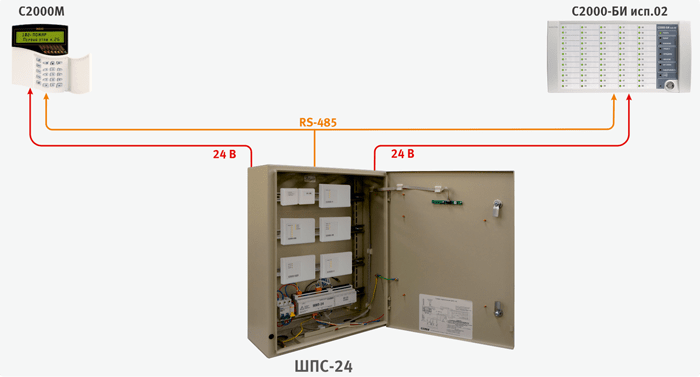
For compact placement of fire alarm and automation devices at the facility, cabinets with redundant power sources can be used: ShPS-12, ShPS-12 isp.01, ShPS-12 isp.02, ShPS-24, ShPS-24 isp.01, ShPS-24 Spanish 02.
These devices are a metal cabinet in which ISO Orion devices can be installed: Signal-10, Signal-20P, S2000-4, S2000-KDL, S2000-KPB, S2000- SP1", "S2000-PI" and others that can be mounted on a DIN rail. The units can also be mounted on the front door using the optional DIN rails provided. mounting kit MK1. The ~220V circuits are protected by circuit breakers. Two 12 V batteries with a capacity of 17 Ah are installed in the cabinet.
Installed inside the cabinet:
ShPS-12 isp.01/ShPS-24 isp.01 are equipped with a window through which it is possible to visually control the devices installed inside. ShPS-12 isp.02/ShPS-24 isp.02 have a degree of protection of the housing IP54.
Fire safety is an important aspect of human life. Each of us, while at work, at home or anywhere else, must be protected from external threats, including from fire. Timely detection of the source of danger can help to quickly find and eliminate it, protecting more than one life, as well as minimizing material costs. Aspiration detectors are an effective way to ensure the safety of people and premises, protect them from fires. About the features of these devices will be discussed in the article.
The word "aspiration" is of Latin origin. Aspiro means "I breathe in". It is this word that gives an idea of the general mechanism of the device. In an aspiration fire detector, it consists in the selection of air masses within a certain controlled room. The extracted air is analyzed in order to timely detect threats and identify combustion products.
The main task for which specialists developed such a device is to search for areas where the fire has just begun to spread and has not yet created a serious danger.
Aspirating detectors, according to experts, today account for 12% of the entire fire systems market in Europe. Their forecasts indicate that this figure will only grow. The development of new types of aspirators makes it possible to use the device more actively, expanding the scope of its use, as well as to fully realize in practice all the advantages of such systems in a wide variety of fields of activity.
The technology, thanks to which the detector works, is one of the most advanced among similar devices aimed at early detection of a fire source. The idea is to create a flow of air that the system absorbs directly from the controlled room, as well as its further transmission to a special optical fire detector. Aspiration thanks to this mechanism of work can detect a fire at the earliest stages of their occurrence - even before a person can feel or see the smoke. The device will fix the danger even in the process of smoldering objects, heating surfaces (evaporation of an insulating substance on cables, etc.).
The aspiration fire detector IPA consists of a series of pipes combined into a system where there are special openings for taking air masses and an aspiration device equipped with a turbine to maintain the air flow.

The principle of operation of the device is quite simple, but effective. The sensors that are installed in the system carry out optical control of the received air. Given the level of required sensitivity of the device, laser or LED detectors can be installed in it. The pipes are mounted in the room where it will be carried out, while the aspiration device - the control unit, is located in any other place from where it is convenient to maintain and control the system.
To date, aspiration detectors equipped with ultra-sensitive laser smoke detectors provide the most successful fire protection. Such systems are excellent for ensuring the fire safety of power plants with various energy production principles, large hangar rooms with aviation, automotive and other types of equipment, rooms designed to store fuel and combustible mixtures, industrial areas of increased sterility, hospital buildings with diagnostic equipment and other premises. with high tech devices.
Initially, the systems were developed specifically for objects of increased importance, the safety of which was a top priority. The safety of material assets, large amounts of money, expensive equipment, the replacement of which can lead to serious expenses, as well as stopping the entire production process, is the main goal of aspiration detectors. In such places, it is extremely important to find and eliminate the formed threat as early as possible at the moment when smoldering did not begin, before open fire appeared.

It is equally important to ensure the safety of premises with a large crowd of people. There, the systems must have a particularly high level of sensitivity compared to standard devices. These can be large exhibition centers, cinemas, stadiums, entertainment and shopping centers. At facilities of this kind, a preliminary signal, which is received only by the maintenance personnel of the building, makes it possible to eliminate the cause of the fire without resorting to mass evacuation, and, accordingly, to panic among visitors.
The IPA aspiration detector has a number of advantages compared to traditional systems:

An aspiration system will help ensure the safety of valuable equipment and people at a high level.

Efficiency of work will avoid serious material costs, stopping the production process and human casualties, without requiring complex maintenance or large investments in its installation.
Aspiration smoke detectors are sophisticated active fire detection devices that provide a reliable warning or alarm signal at the earliest stages of the appearance of signs of a fire. Aspiration fire smoke detectors consist of a detector unit with an aspirator and a piping system with air sampling holes through which air samples from the controlled space are delivered to the detection device (Fig. 1). This design of the detector allows you to isolate the measuring chamber from external influences as much as possible. High sensitivity, which in some models reaches 0.0015% / m (0.000065 dB / m), is many times higher than the parameters of point detectors and is achieved through the use of ultra-sensitive optical density meters. Aspiration detectors are used to control not only premises, but also equipment, air conditioning installations and air ducts. The use of aspiration detectors provides the highest level fire protection of any object, and the specific design and additional devices allow them to be used even where the use of other types of detectors will be ineffective or simply impossible.
On the this moment technical requirements for aspiration detectors are established in GOST R 53325-2009 “Fire fighting equipment. Technical means of fire automatics. General technical requirements. Test Methods". In this article, we will not dwell on the technical characteristics, but consider the possible applications and advantages of installing aspiration detectors on various types objects.
In Russia, the basic requirements for the design and installation of aspirating fire detectors are defined by the Code of Rules SP 5.13130.2009 “Fire protection systems. Fire alarm and fire extinguishing installations are automatic. Norms and rules of design». And here the first point is the recommendation to install aspiration detectors to protect large open spaces. These areas include atriums, production shops, warehouses, trading floors, passenger terminals, sports halls, stadiums, etc. According to clause 13.9.1, class A aspiration detectors can be installed in rooms up to 21 m high, class B - up to 15 m, class C - up to 8 m. in a room with a height of more than 12 m, unlike linear smoke detectors, installation of a second tier of detectors is not required. Building structures usually impose certain restrictions on the installation sites of linear smoke detectors in such premises, forcing them to be mounted at a certain distance from the ceiling, which in turn seriously reduces the level of fire protection of the premises and the facility as a whole. Aspiration detectors do not have these disadvantages. Piping with air sampling holes can pass directly under the ceiling, avoid obstacles, while expanding the controlled area and reducing the likelihood of false alarms.
Moreover, in accordance with SP 5, it is allowed to embed air sampling pipes in building construction and finishing elements. This application makes it possible to protect rooms with high design requirements, such as historic buildings, museums, large area glazing, etc. Moreover, the elements of the fire alarm system in this case are really invisible, and the level of fire protection remains at the highest level.
The air intake pipes can be laid both in horizontal and vertical planes, which makes it possible to determine the best option for access to the detector for maintenance and repair at the system design stage and place it in the most convenient place for this. Suppose you want to monitor limited hard-to-reach spaces, such as space behind a false ceiling and under a raised floor, cable duct, inner space aggregates and mechanisms, such as escalators or conveyor lines. And here, according to SP 5, the use of aspiration fire detectors is allowed. It is allowed to control both the main and allocated space of the room, i.e. in the case of monitoring the overhead space, the pipes of the aspiration detector are located behind the false ceiling, and additional capillary tubes lead the air sampling holes into the main space. Particular attention should be paid to the protection of expensive equipment and material assets. The use of highly sensitive aspiration detectors when protecting, for example, servers or data arrays, even overheating of individual components can be detected electronic device. The advantage of aspirating detectors is that the pipe or capillary outlet with an air intake is led directly to the object to be protected. Figure 3 shows an example of equipment cabinet protection. Server rooms, data processing centers, warehouses with rack storage and other facilities where it is extremely important to detect and eliminate the source of ignition at the earliest stage in order to prevent major damage are equipped in the same way.
Often there are objects, the control of which by traditional methods is complicated by difficult conditions, such as dust, dirt, extreme temperatures, high humidity, electromagnetic interference, high air flow speeds, etc. The use of aspiration detectors here is also an effective way of protection. Since air sampling from controlled volumes is carried out through small holes, air flows from ventilation and air conditioning systems do not affect the detection ability. That is why it is possible to place the air intake pipes of the aspiration detector directly in the air ducts and on the air intake grilles. If the operating conditions are associated with significant contamination or dustiness, then additionally installed in the pipeline system external filters(Fig. 4).
Protecting the measuring chamber of the instrument from foreign particles entering it reduces the likelihood of false alarms and prolongs the life of the system. In the most severe conditions, for example, in waste processing plants or in industrial production, additional provision is made for purging the pipeline into reverse direction. To do this, a valve is installed, which, when blowing, cuts off part of the pipe to the detector unit, after which the contaminants are blown out of the pipeline. And in some cases, when blockages in pipes can happen too often, it may be advisable to implement automatic cleaning of the pipe system.
| Rice. 3. Location of pipes when protecting cabinets with equipment |
|
Rice. four. Three-level replaceable filter for air purification |
|
Rice. 5. Condensate extraction device (FAS*ASD*WS) |
|
Rice. 6. Example of a pipeline with a condensation protection device |
In the case of monitoring areas with changing temperature or incoming fresh air condensation may form in the aspiration system, which may impair the performance of the detector unit. However, there is a solution for this case as well. Piping in areas with high humidity
equipped with an additional device for collecting condensate (Fig. 5).
In addition to protecting the detector unit from moisture ingress, these devices may have a filter for additional protection against particulate matter. It is installed at the lowest point of the pipeline (Fig. 6). And additional pipe turns at an angle of 45 ° allow you to provide access to it during maintenance.
The solution described above is used in areas with temperatures from 0° to 50° C. But the range of operating temperatures during the operation of aspiration detectors is much wider and allows them to be used even at negative values in deep-freeze warehouses. The detector unit itself, depending on the optical density meter used, can operate at temperatures from *20° C to +60° C.
When installing suction systems, halogen-free plastic pipes are usually used. PVC pipes allow them to be used at temperatures from 0° to 60° C. ABS plastic pipes can be used in the range from *40° to +80° C. Nevertheless, the detector unit is most often taken out of the area with difficult conditions. This further expands the scope of this type of detectors. Let's consider one more example. Agree, it is quite difficult to find a suitable detector to protect the sauna. Some models of aspiration detectors can perform their detection functions at air sample temperatures up to 110 ° C. Of course, plastic pipes are no longer suitable for this example, and in order to exclude false alarms, it is imperative to use a condensate extraction device.
There are several other areas of application related to the possibility of moving the detector unit outside the controlled area. plastic pipes are not conductors and are not subject to
the influence of electromagnetic interference. Such a system can be operated even in conditions of high radiation. In turn, the remote block of the aspiration detector does not create interference in the controlled area, which is very important for diagnostic and testing laboratories.
Many mistakenly believe that the absence of loop conductors in the controlled area will allow the use of aspiration detectors in explosive objects in a similar way. Such a solution does exist, but the situation is somewhat more complicated. Indeed, in this case, it is not air that enters the measuring chamber, but an explosive gaseous mixture, and the detector unit itself, at certain values of its composition, concentration, temperature and pressure, can become a source of ignition. To prevent the spread of flame through the pipeline and detonation in the explosive zone, special explosion-proof barriers are used in the system (Fig. 7).
As we can see, the possibilities of aspiration detectors are wide and varied. The properties of aspirating smoke detectors, compared to traditional point and other types of detectors, are unique: high sensitivity for early detection, and the ability to install in large spaces, and the ability to work in difficult conditions, and ease of maintenance even in hard-to-reach places. Undoubtedly, the regulatory framework created in 2009 will allow suction systems occupy its niche in the Russian market of fire detectors and improve the fire safety level of many facilities.
INSTRUCTIONS AND PROPHECIES OF THE Blessed MOTHER ALIPIA GOLOSEEVSKY, Kyiv...

Eufillin dropper in ampoules is used to treat pathologies that ...

Among all ointments for the treatment and prevention of joint diseases, the most ...