 ML 110×125 Vs (screw-cutting)
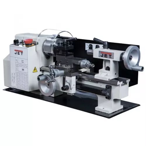


Individual entrepreneur details in the contract include mandatory and additional information....


The manufacture of metal products is a progressive and unrivaled business in the market. It is not surprising that everything more people study the technology of creating parts of varying complexity, but such work requires a lathe. Although the industrial type installation is safe, reliable and easy to use, not everyone can buy it. Therefore, many assemble the machine on their own. This requires appropriate instructions, materials and a little patience.
AT household lathe is an indispensable thing. Of course, it is better to buy an industrial unit that will be reliable and durable, but this is an expensive thing. In addition, the industrial installation is bulky, it will not work to place it in a residential area.
Assembly machine is a good option to save money and space. It will not be as functional, but it will perfectly cope with the processing of metal parts, threading, knurling corrugated surfaces and creating the necessary geometric shape.
Even a beginner in turning can master such a device. Easy control allows you to handle metal parts without outside help and constant questions. The minimum dimensions fit such a unit on small table, and the materials from which it is assembled can be easily replaced with new ones in the event of a breakdown.
Self-made assembly expands the choice of installation type and makes it multifunctional in terms of processing various materials
. Some machines are suitable for woodworking, while others are better suited for different qualities of metal material. At this stage, it is important to decide on your preferences and the purposes for which it will be used.
Before you start assembling a homemade lathe, you should study the device of the simplest installation. The connection of various nodes and the mechanism of work will give more understanding during assembly and during operation. In addition, there will be something to rest on in case of deformation or breakage of a home-made installation.
The main parts of the mechanism are:
Industrial units slightly different in design, but some parts are easy to replace with analogues. For example, the frame acts as a place for attaching the main mechanism. It's usually big metal body, but in case self assembly a strong frame of small dimensions is used. The tailstock moves along the frame or, as it is commonly called in the turning industry, “bases”. The headstock is installed to accommodate the main equipment assembly and is fixed in a stationary state.
Refer to the transfer center Special attention, because it connects the leading center to the electric motor. Usually it is in this part that the main breakdowns lie. Through this part, the voltage is transmitted, which is required to rotate the workpiece.
 Assembling homemade turning equipment involves the use of high-quality and durable materials. For the bed, a metal base, corners and profiles made of durable steel are better suited. This will allow you to securely fix the installation centers. Some experts prefer a wooden frame, but this material is more suitable for devices with low power and performance. Otherwise, the wood will quickly deform, and the fixed center will shift.
Put on a lathe motors power of 200 watts or more. The weakest are able to cope with the processing of wood, but no more. It is from these criteria that one should proceed, because the motor directly affects the power and productivity of the machine. The more powerful the motor, the faster and more accurately it will be able to process parts. For processing metal parts, a powerful and reliable motor should be installed.
The last thing you should pay attention to is the way of rotation. In homemade machines, a chain or belt design is used. The latter option is used more often because of its reliability and ease of replacing a worn belt. In addition, the torque when using belts is better and more uniform than when using chains.
Exist models and without transmission part. Typically, such a design is built so that the leading center is attached directly to the motor shaft. Various schemes, video assembly of metal lathes will help in this difficult task.
One of the features of the assembly of the installation is to suppress the vibration that is caused by the operation of the motor. To absorb it, a leading and a driven center is installed, but the mechanism can be changed. The bottom line is to use one leading center, but additionally put a chuck or faceplate.
 With electric motor it's also not that simple. Many years of practice shows that it is best to abandon the choice of a collector type of electric motor. The reason is simple. The engine is operated in such a way that the torque increases when there is no load, even without a command from the turner. At a certain moment, the mechanism and design of the machine simply cannot withstand the load, and the parts, the workpiece fly off in different directions.
Similar "shooting" metal parts greatly harm the environment in an apartment or house, not to mention the injuries that can be inflicted on a person during work. If you plan to install exactly the collector type of motor, you must take care of a special gearbox in advance, which will prevent uncontrolled acceleration.
The best option among electric drives is asynchronous type. The advantage of this system is that it is resistant to loads and does not change the speed without control. This greatly reduces the risk of deformation of the machine. In addition, its power is enough to process parts with a width of about 70 cm and up to 10 cm in length. For some materials, this power will be superfluous, so the electric motor is selected solely for the material and dimensions of the parts to be processed. The more complex the shapes, cutouts and carvings, the faster the rotational effect should be.
The driven center, as already noted, must be stationary, but there are cases when it is made rotating. This will not give the best result, but it will have to be replaced regularly. Usually, when it comes to do-it-yourself machine tools, the driven center is made of a metal bolt, in which the threaded section is sharpened to a cone. Next, the prepared part is installed in a thread pre-cut on the tailstock. Its stroke is 2-3 cm. This installation allows you to press the workpiece between the two centers of the lathe.
 - this is one of the main details in the machine, which, in principle, starts the process of work. The processing of parts depends on the power of the electric motor. There are two categories of electric motors that are suitable for installation on a machine:
Naturally, these are symbols, and not only the size of the workpiece plays a role, but also its brand. Carbide products require a lot of impact power to get the final product.
A homemade lathe does not have to have a powerful electric motor, because many process wood or assemble a simple grinder. In this case, electric motors are suitable even sewing machine. The drive is simply mounted on the unit, and then a hollow shaft is connected and a belt or chain transmission is connected. With a pulley, which is fixed on the key, the shaft is connected. A pulley is necessary, because a workpiece will be installed on it for further processing.
 The shaft allows you to make the machine multifunctional thanks to various transitions. With some, a grinding disc is installed, others are suitable for drills. Everything is easily replaced depending on the purpose of processing blanks.
Power mechanisms they are easily connected to the installation, but if there are no necessary skills and experience, then it is better to invite a specialist. This gives reliability and electrical safety, because electricity will be supplied to a unit consisting of metal. When working with it, even a slight mistake in the installation of the electric motor can lead to electric shock.
The simplest lathe, which is easy to do with your own hands, is a beam lathe. It is suitable for processing low grade metal workpieces. That is, the products are sharpened, the structure is turned. Especially popular are sharpening knives, making keys and creating parts for cars.
For Assembly unit will need:
At the beginning of work, you will need to prepare two simple wooden racks to which bolts will be attached. The machine frame is attached to the bolts. The frame is often made of wood, but a more reliable material is grade metal or steel channels. The metal construction is durable and securely holds the mechanism in place, without shifting it during operation.
 Next step- this is the manufacture of a handpiece, which is responsible for the stability of the cutter when working with metal products. It is easy to make such a handkerchief yourself. All that is needed is to glue two planks at right angles and connect the resulting structure with screws. A thin metal plate is installed on the lower part of the handpiece, which will prevent the working tool from changing the shape during rotation. Depending on the frequency of work on the machine, the metal plate will need to be changed when it deforms. A plank that stands horizontally is needed to control the movements of the handbrake. They make a hole in it.
There should be no issues with the manufacture of the tailstock and headstock. These are simple structural details that even a beginner can do. In any case, there are a large number of all kinds of videos and instructions on the Internet that clearly show exactly how grandmothers are made and what material is best to choose for this. Headstock chucks are made from ready-made cylinders, which are suitable in cross section for the design of the machine. Sometimes cartridges are made independently by welding several sheets of iron.
It is not difficult to assemble a mini-turning machine for metal on your own. Basically, you should be patient and study the videos and literature, which describe in detail the features of the assembly home machine. In this work, the main thing is not to rush, select durable material and observe safety precautions. In moments when there is not enough knowledge, and especially when it comes to installing an electric drive, it is better to turn to specialists. All other stages of assembling a lathe are easy to handle, even if there is no experience in this matter.
Every home craftsman would like to have a metal lathe in his arsenal of tools. Such equipment allows, if necessary, to carve a broken part, cut a thread, make some kind of trinket, and much more. However, since not everyone can afford industrial units, and they take up a lot of space, most craftsmen prefer to make compact home-made metal machines with their own hands.
Read in the article
Household mini lathes, as well as similar industrial equipment, designed for processing metal blanks and giving them a cylindrical, conical and spherical shape. Now they are used in almost all industries, which makes it possible to reduce human participation to almost zero, but a simple machine is suitable for home needs. Despite the fact that compact turning equipment has inherited most of the functions from its large counterparts, however, it can only be used to machine small workpieces and parts. Also on mini-machines, you can make end trimming and perform external and internal threading, boring and much more. Compact turning equipment is perfect for, home, installation on or in a small.

For the most part, industrial and household lathes are similar. The difference lies in functionality, power and weight. The figure below shows the device of a typical screw-cutting lathe. The main nodes are:


One of the main elements is the frame - a massive metal base on which all the main components and parts of the equipment are mounted. It must be strong enough, and the mass must be such as not to allow the machine to tip over during operation. For the floor version, massive supports (pedestals) are added.

The lathe caliper is designed to move along, across and at an angle to the axis of the spindle of the cutters fixed in the tool holder. The device has a cross structure, consisting of three main elements: carriage, transverse and incisal sleds.

The headstock is one of the most difficult parts of a lathe, especially for self-manufacturing. It contains a gearbox with a spindle and a control unit. Under the casing of the headstock is an electric motor, which is connected by a belt drive to the gearbox pulley.


This unit contains a block consisting of interchangeable gears designed to transmit and change the spindle speed and torque from the feed box shaft. You can buy a lathe headstock or make your own.


The tailstock of a metal lathe is movable and is designed to press the workpiece to the center of the spindle. One of the elements of this assembly is a quill, on which a fixed or rotating center is installed, resting with its tip against the workpiece. The workpiece is installed in the chuck on the spindle and supported by the tailstock. Thus, reliable fastening of the part for its high-quality processing is ensured.

Drills, taps, reamers, etc. can be installed in the tailstock. When installing and moving on the skids of the bed, it is necessary to avoid sharp and strong blows along the body of the assembly to prevent displacement of centers.


The tool holder is intended for fixing a tool for metal processing on the support of a lathe and moves both in the longitudinal and in the parallel direction relative to the workpiece. There are two types of tool holders: two- and four-position. In the first case, you can simultaneously install two cutters with screws, and in the second - four, which allows you to quickly change the cutters if necessary without stopping the lathe. For quick change of incisors, a special handle is provided.


Making a mini lathe for metal with your own hands is not so difficult as it might seem at first glance. You just need to compose detailed plan actions, drawing, prepare the necessary materials and tools, and, of course, some skills, and a great desire.

This stage is the most important, since the correct execution of all further operations and the correct operation of the equipment depend on it. First of all, you need to determine the dimensions of the machine. The average dimensions of equipment used in everyday life is 900×350×300 mm. You should not deviate much from these values, as this will lead to the fact that it will be inconvenient to work, and performance will decrease significantly.


Having decided on the drawing and dimensions of a small lathe, we proceed to the preparation of the necessary materials.
| Illustration | Action Description |
 | The cast iron frame can be replaced by a frame made of steel angles and shaped pipes. Do not use wood, because in this case you should not rely on the durability of the machine and the accuracy of the work performed. |
  | As a power unit, it is preferable to take a low-power asynchronous electric motor, since even with a sharp decrease in speed, the drive will not break. Engine power must be selected in accordance with the expected diameters of the workpieces. |
 | Choose from different diameter drive belts. |
  | As fasteners we use a set of bolts and nuts of various diameters and lengths. |
  | Steel bar slides are made from steel bars, which are recommended to be hardened. You can also use ready-made elements from a suitable used factory-made machine (this also applies to other equipment components). |
    | The spindle and "tailstock" are considered the most difficult components for self-manufacturing, so you can contact a specialized workshop or the manufacturer. If it is decided, nevertheless, to make these details on your own, then the headstock can be made of metal of the appropriate thickness and. A simple spindle is made from a pointed bolt, nuts, and a handwheel. |
  | The feed longitudinal and transverse screws can be machined on a machine in a specialized workshop or made independently from rods with threads already cut. |
  | To create rotating assemblies, rolling bearings mounted on the housing are suitable. |
  | The caliper can be made from a steel plate with a thickness of 8 mm. |
  | The tool holder is made of a thick steel plate, ordered in a specialized workshop or taken from another machine. |
After the drawing has been selected and all the necessary materials and components have been prepared, you can begin to assemble the unit.
The electric motor is the most important element lathe for metal, whether industrial production or homemade. It is he who is responsible for the operation of the equipment. The functionality of the lathe largely depends on the power of the electric motor. If the machine is intended to work with small workpieces, then an engine with a power of up to 1 kW will suffice (you can, for example, take from an old sewing machine or). For large parts, you will need a power unit with a power in the range of 1.5–2 kW.


In order for the lathe to work properly, it is important to assemble it correctly, and for this you just need to follow the following algorithm:

If desired, conventional turning equipment can be re-equipped with your own hands into a metal milling machine.
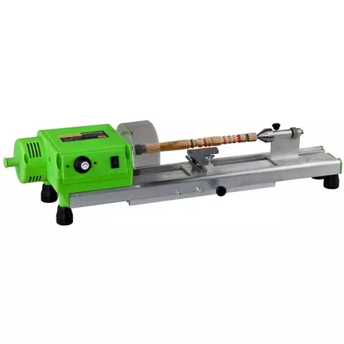
You can also make a lathe from an electric drill, but basically this design is suitable for woodworking. Of course, it can be used to work with metal, but the power unit used must be as powerful as possible, and the parts must be very small. For example, such a machine is suitable for a homegrown amateur jeweler. This design consists of a minimum of parts. So, let's move on to step-by-step instructions for making a lathe from a drill with a photo and description.
| Illustration | Action Description |
 | On the |
If in chores there is often a need for turning parts, trimming or sharpening tools, you can purchase the appropriate installation. But for small amounts of work at home, you can make a homemade metal lathe.
The machine is made for their own business purposes. The complexity of the design and the power of the engine depend on this. In general, it can perform the same work as professional installations:
Thanks to such wide functionality, this device can be used to sharpen knives, repair some car parts, cut metal structures, etc.

At the same time, making a lathe with your own hands is more profitable option, insofar as:
A home-made metal lathe as a do-it-yourself device has a number of operational features that are important to consider when working on it:
On the preparatory stage it is important to understand which constituent parts will consist of a future lathe for metal. Based on this, suitable units and parts are selected from improvised materials. It is important to take into account exactly what tasks the mechanism will be oriented towards and what it will be used for.
In principle, the installation should consist of the following elements:
The scheme of the finished device is shown in the photo.

When all the parts are in stock, you can draw up a basic drawing of the product. The following drawings can be taken as a basis.

Lathe assembled, its main elements can be seen here.
NOTE. It is best to make a lathe for metal with your own hands from metal products (pipes, corners, etc.). Any wooden structure is short-lived, and it will be much more difficult to work with the part.
Further actions consist in the manufacture of a support installation (bed), installation of working equipment, connecting it to an electric motor and direct commissioning. The sequence of actions is as follows:

After that, the bed is fully assembled. It is important to take into account that all elements are tightly connected - the slightest slack is unacceptable, because during operation, vibrational swings will increase the fragility of the mechanism and can lead to damage.
Visual instructions for mounting the bed - in this video.
Further work is aimed at mounting the mechanism itself and fixing it on the working surface. The algorithm is the following:

It is important to do the first start at idle, and then check the operation of the entire device on a rough metal part.
To use the device in a city apartment, it is quite realistic to create a home-made metal lathe from a conventional drill in a few hours. It will serve both as an engine and a rotating mechanism. The design is not so powerful, but it is quite suitable for small tasks.

It is desirable to mount the drill to a metal structure - optimally the old one will do rack.

The manufacturing algorithm is as follows:

Handles installation and wooden products- with its help you can apply a simple relief carving on wooden blank as shown in the video.
HELPFUL ADVICE. Working on a lathe from a drill is not limited to cutting parts and sharpening. You can install a copier on it, with the help of which perfectly similar parts are obtained at home in a matter of minutes.

Often, for economic purposes, a small home-made lathe for metal is required - here is a video with a visual step by step instructions for its manufacture.
Compliance with certain rules when working on the machine is mandatory, especially when it comes to a product made by oneself.
Immediately after assembly, you should run the machine for a few minutes at idle and listen to the sounds of the engine: they should be uniform, without extraneous noise. Preparation for work consists of the following steps:
During work, you must adhere to the following rules:
A visual illustration is presented in the diagram.

A visual technology for working on a do-it-yourself metal lathe is presented in the video.
Care of the mechanism is an essential condition for its long-term trouble-free operation. Several rules must be observed:
NOTE. Lubrication should not get on the drive belts, because in this case the friction is greatly reduced, the belt slides over the surface of the pulley, as a result of which the tension is weakened.
If you need a professional tool for large volumes of complex work, you should figure out what types of metal lathes exist.
The schematic diagram of the device is shown in the figure.


Depending on their purpose and features of the device, several types of metal lathes are distinguished:
This is the most popular type of devices - with their help you can process parts inside and out, work with flat, conical and cylindrical surfaces. Can be carried out complex work for cutting precise threads, processing the ends of parts and drilling holes of almost any diameter.


Depending on the location of the bed, there are such types of machines:


Depending on the features of the feed of the workpiece, as well as on the specific type of metalworking, the following types of work on a lathe are distinguished:
In this case, it is important to set the tip of the cutting part so that it is slightly below the axis with the workpiece. If this is not possible, then it is better to install another tool or grind the part.
Often, when carrying out such work, the tailstock is not needed - then it can simply be removed
NOTE. If it is not possible to securely fix the workpiece in the chuck, a steady rest can be used.

Many models provide the ability to automatically feed the workpiece. In this case, the cutting part should be located to the right of the workpiece.
While working, it is best to always keep left hand free to immediately press the emergency stop if the workpiece goes astray from the desired direction.
The sequence of actions is as follows:

Features of the technology of turning a cone on universal machine shown in the video.
On lathes, you can perform internal or external thread on the workpiece. The thread is applied to both cylindrical and conical products. There are three types of profiles:

Technologically, the process is performed using the sharp tip of the cutter. The cutter is mounted in the caliper and moves with it, leaving marks on the metal product at a certain interval.
The cutters can be either solid or prefabricated with fasteners. They are also made with soldered blades - they are especially durable, since the blades are made of strong alloys (brass).
For correct drilling, it is important to prepare the end face of the workpiece especially well. It is cut so that the surface is as even as possible. Also, a slight recess must be made at the end so that the work can be done exactly in the intended place. The recess can be made with a drill or cutter.
The size of the holes is adjusted by installing the appropriate drill. If the hole is made smaller, reaming can be done - that is, obtaining a larger hole due to a wider drill.
It is not difficult to make a lathe for metal with your own hands. The main thing is to choose the right electric motor with the parameters suitable for the job and ensure the rigidity of all structural connections.
Elements and cutting conditions
Before talking about processing methods, let's briefly get acquainted with the elements and cutting mode.
Here we will meet new concepts: depth of cut, feed, cutting speed.
All of them are interconnected, and their value depends on various reasons.
The depth of cut is the thickness of the metal layer removed in one pass of the cutter. It is denoted by the letter t and ranges from 0.5 to 3 or more millimeters for roughing to tenths of a millimeter for fine turning.
Feed is the movement of the cutter along the surface to be machined. Numerically, it is expressed in millimeters, denoted by the letter S and indicates the amount of displacement of the cutter per revolution of the part. Depending on the strength of the material being processed, the rigidity of the machine tool and the cutter, the feed rate can vary from 0.1-0.15 mm / rev to 2-3 mm / rev at high-speed cutting conditions. The harder the metal, the lower the feed should be.
The cutting speed depends on the number of revolutions of the spindle and the diameter of the part and is calculated by the formula.
When choosing one or another cutting speed, it is necessary to take into account the hardness of the material being processed and the tool life, which is measured by the time of its continuous operation until it becomes dull in minutes. It depends on the shape of the cutter, its dimensions, the material from which the cutter is made, on turning with or without a cooling emulsion.
The cutters with hard alloy plates have the greatest resistance, the cutters made of carbon steel have the least.
Here, for example, what cutting speeds can be recommended when turning various materials with a high-speed steel cutter. Its durability without cooling is 60 minutes.
Approximate data on the cutting speed of metals:
Turning smooth cylindrical surfaces
Smooth cylindrical surfaces of parts are turned with through-cutting cutters in two steps. First, with a rough cutter, a peeling is performed - a rough turning - quickly removing the bulk of the excess metal. The figure shows a straight cutter for roughing:
Rough cutters: a - straight; b - bent; c - Chekalin's designs.
The bent cutter is convenient when turning the surface of the part near the chuck jaws and for trimming the ends. Usually incisors have a working stroke only in one direction, most often from right to left. A double-sided through-cut cutter designed by the innovator turner N. Chekalin makes it possible to eliminate the back-idling of the cutter, reducing the processing time.
After turning with a rough cutter, large risks remain on the surface of the part and the quality of the machined surface is therefore not high. For final processing serve as finishing cutters:

Finishing cutters: a - normal; b - with a wide cutting edge; c - bent, designed by A.V. Kolesov.
The normal type of finishing cutter is used in turning with small depth of cut and low feed. A fine cutter with a wide cutting edge allows high feed rates and a clean and smooth surface.
Trimming ends and ledges
To trim the ends and ledges on a lathe, they usually use scoring cutters. Such a cutter is shown in the following figure:

Cutting in the centers: a - cutting cutter; b - cutting the end with a half-center.
It is best used when turning parts in the centers. In order for the end face to be machined as a whole, a so-called half-center is inserted into the tailstock.
If the part is fixed with only one of its ends - when machining in a chuck - then a bent cutter can also be used for turning the end. For the same purpose and for turning the ledges, special scoring thrust cutters are used, which work with transverse and longitudinal feed.

Trimming the ends: a - trimming with a bent cutter, b - scoring thrust cutter and its work.
When cutting ends and ledges, the young master must ensure that the top of the cutter is always set strictly at the level of the centers. A cutter set above or below the centers will leave an uncut ledge in the middle of the solid end.
Grooving
For turning grooves, slotted cutters are used. Their cutting edge accurately reproduces the shape of the groove. Since the width of the grooves is usually small, the cutting edge of the kerf has to be made narrow, so it is rather brittle. To increase the strength of such a cutter, the height of its head is made several times greater than the width.

For the same reason, the head has a small rake angle.
Cut-off cutters are very similar to slotted cutters, but have a longer head. A narrower head is made in order to reduce material consumption when cutting.
The length of the head should be selected according to the dimensions of the part and be slightly more than half of its diameter.
When installing slotted and detachable cutters, you must also be very careful and accurate. Careless installation of the cutter, for example, its slight distortion, will cause the cutter to rub against the walls of the groove, marriage in work, breakage of the tool.
Turning narrow grooves is carried out in one pass of the cutter, which is selected according to the width of the future groove. Wide grooves are machined in several passes.

The order of work is as follows: using a ruler or other measuring instruments, mark the boundary of the right wall of the groove. Having installed the cutter, they machine a narrow groove, without bringing the cutter 0.5 mm to the desired depth - the rest for the finishing pass. Then the cutter is shifted to the right by the width of its cutting edge and a new groove is made. Having thus chosen a groove of the intended width, the final, finishing pass of the cutter is made, moving it along the part.
The workpiece installed in the centers should not be cut to the end: the broken part can damage the tool. A short piece clamped in the chuck can be cut clean using a special beveled cut-off tool.

The feed rate and cutting speed for grooving and cutting off should be less than for cylinder machining, because the rigidity of the through and parting cutters is not large.
Cone turning
In the practice of a young turner, turning cones will be less common than other work. The easiest way is turning small cones (no more than 20 mm) with a special wide cutter.

In the manufacture of an outer or inner cone on a part fixed in a chuck, a different technique is used. turning upper part corner caliper, half the angle of the cone at its apex, the part is machined by moving the cutter with the help of the upper slide of the caliper. This is how relatively short cones are sharpened.
To make long and gentle cones, you need to shift the rear center, move the tailstock a certain distance towards yourself or away from you.

If the part is fixed in the centers in such a way that the wide part of the cone will be at the headstock, then the tailstock should be shifted towards you, and vice versa, when the tailstock moves away from the working one, the wide part of the cone will be on the left - at the tailstock.
This method of taper turning has serious shortcoming: due to the displacement of the part, rapid and uneven wear of centers and center holes occurs.

Interior surface treatment
Hole machining can be done with various tools, depending on the required surface shape and machining accuracy. In production, there are blanks with holes made during casting, forging or stamping. For a young metal worker, ready-made holes will be found mainly in castings. The processing of holes in solid workpieces that do not have prepared holes will always have to start with drilling.
Drilling and reaming
Shallow holes on a lathe are drilled with spade and spiral (cylindrical) drills.
The spade drill has a flat blade with two cutting edges, turning into a rod. The angle at the top of the drill usually has 116-118 °, however, it can be, depending on the hardness of the material, from 90 to 140 ° - the harder the metal, the greater the angle. The accuracy of the hole when processing with a pen drill is small, so it is used when high accuracy is not required.

Twist drills are the main tool for drilling. The processing accuracy of these drills is quite high. A twist drill consists of a working and part of a conical or cylindrical shank, with which the drill is mounted in the tailstock quill or in the chuck.

Spiral drills: a - with a conical shank; b - with a cylindrical shank
The working part of the drill is a cylinder with two helical grooves forming the cutting edges of the drill. Chips are brought out along the same grooves.
The drill head has a front and rear surface and two cutting edges connected by a bridge. Chamfers running along the helical grooves guide and center the drill. The value of the angle at the top of the twist drill is the same as the feather drill and can vary within the same limits. Drills are made of alloyed or high-speed steel. Sometimes alloy steel drills are equipped with carbide inserts.

The drill is fixed in two ways, depending on the shape of the shank. Drills with a cylindrical shank are fixed in the tailstock quill using a special chuck, drills with a conical shank are inserted directly into the quill hole.

It may happen that the taper shank is small in size and does not fit the hole. Then you have to use the adapter sleeve, which, together with the drill, is inserted into the quill.

Adapter sleeve for drills with tapered shanks: 1 - drill shank; 2 - bushing.
To push the drill out of the quill, you need to rotate the handwheel to tighten it into the tailstock housing. The screw will rest against the drill shank and push it out. With the help of a special holder, you can also fix the drill in the tool holder.
When drilling, care must be taken to ensure that the drill does not lead to the side, otherwise the hole will be incorrect and the tool may break. The drill is fed by slow and uniform rotation of the tailstock handwheel or by moving the caliper if the drill with the holder is fixed in the tool holder.
When drilling deep holes, it is necessary from time to time to remove the drill from the hole and remove chips from the groove.
The depth of the hole should not exceed the length of the working part of the drill, otherwise the chips will not be removed from the hole and the drill will break. When drilling blind holes to a given depth, you can check the drilling depth by divisions on the quills. If they are not, then a mark is made with chalk on the drill itself. When a characteristic screech is heard during drilling, this means that either the drill is skewed or it is dull. Drilling must be stopped immediately by removing the drill from the hole. After that, you can stop the machine, find out and eliminate the cause of the squeal.
Reaming is the same drilling, but with a larger diameter drill through an existing hole. Therefore, all drilling rules apply to reaming.
Other methods of processing internal surfaces
In the practice of a young turner, there may also be such a case when the diameter of the desired hole is much larger than the diameter of the largest drill in its set, when a groove needs to be made in the hole or made conical. Each of these cases has its own processing method.
Boring holes is carried out with special boring cutters - roughing and finishing, depending on the desired cleanliness and accuracy of processing. Roughing cutters for turning blind holes are different from roughing cutters for turning through holes. Finishing of through and blind holes is carried out with the same finishing cutter.

Boring cutters: a - rough for through holes; b - draft for blind holes; c - finishing
Boring has its own difficulties compared to external turning. Boring cutters have low rigidity, they have to be significantly extended from the tool holder. Therefore, the cutter can spring and bend, which, of course, negatively affects the quality of processing. In addition, it is difficult to monitor the work of the cutter. The cutting speed and feed rate of the cutter must therefore be 10-20% less than with external processing.
Particularly difficult is the processing of thin-walled parts. Clamping such a part in the chuck, it is easy to deform it, and the cutter will select thicker chips on the depressed parts. The hole will not be strictly cylindrical.

For correct processing when boring, the cutter is set at the level of the centers. Then you need to bore the hole 2-3 mm in length and measure the diameter.

If the size is correct, you can bore the hole to its full length. When boring blind holes or holes with ledges, as well as when drilling, a mark is made on the cutter with chalk indicating the depth of boring.


The cutting of the inner ends is carried out with scoring cutters, and the turning of the internal grooves is carried out with special slotted grooving cutters, in which the width of the cutting edge exactly matches the width of the groove. The cutter is set to the appropriate depth according to the chalk mark on the body of the cutter.

Internal groove measurement: ruler, caliper and template
In addition to boring cutters, countersinks are used to bore cylindrical holes. They are similar to twist drills but have three or four cutting edges and are not suitable for making holes in solid material.

Spiral tail countersinks: a - from high-speed steel; b - with hard alloy plates
Very clean and precise cylindrical holes are made with reamers. Both of these tools are not used to expand the hole, but to fit Exact size and form.

Reamers: a - tail; b - back
Making taper holes
Turning the inner cones is perhaps the most difficult task. Processing is carried out in several ways. Often, conical holes are made by boring with a cutter while turning the upper part of the caliper.

In solid material, a hole must first be drilled. To facilitate boring, you can drill a stepped hole. It should be remembered that the diameter of the drill must be selected in such a way that there is an allowance of 1.5-2 mm per side, which is then removed with a cutter. After turning, you can use a conical countersink and a reamer. If the slope of the cone is small, a set of conical reamers is used immediately after drilling.

The last of the main operations performed on a lathe is threading.
Mechanical threading is possible only on special screw-cutting machines. On the simple machines this operation is done manually. Techniques for the manual manufacture of external and internal threads are described above.
Measuring tool
In turning, the same tool is used as in metalworking: a steel ruler, calipers, calipers and others. They have already been mentioned before. New here may be various patterns that the young master will make himself. They are especially convenient when making several identical parts.
Remember that all measurements can be made only after the machine has completely stopped. Be careful! Do not measure a rotating part!
Precautionary measures
When working on a lathe, you must be guided by the following rules:
1) it is possible to start working on the machine only after a detailed acquaintance with the machine and processing methods;
2) not to work on a faulty machine or an unusable (blunt) tool;
3) firmly fix the part and monitor the serviceability of the enclosing devices;
4) do not work in loose clothing: tie sleeves at the wrist, long hair hide under a headdress;
5) remove chips in a timely manner and keep order at the workplace;
6) do not stop the rotating cartridge with your hands;
7) In the event of a malfunction, switch off the machine immediately.

Machine Care
The more carefully the machine is maintained, the better and longer it will work. This simple rule should be firmly remembered and carefully followed. Lathe care is as follows.
The main thing is the lubrication of all rubbing parts. Before starting work, it is necessary to inspect the machine and check whether there is enough lubrication. Bearing lubrication should be monitored most closely by filling grease fittings and lubrication holes with engine oil. The machine at this time, in order to avoid an accident, must be stopped.
After work, you need to clean the machine, remove chips, wipe the guide beds and calipers, and lubricate them with a thin layer of oil.
The taper holes of the spindle and tailstock quills must be absolutely clean. The accuracy of the machine will depend on their good condition.
Before starting work, you should also check the condition of the drive belt. It must be protected from oil splashes and drops, as an oily belt slips and quickly works. The belt tension should not be too strong, but not too weak: a loosely tensioned belt slips, and with a strong tension, the bearings heat up and wear out quickly. The drive belt guard should also be in order.
For a home craftsman with the skills of a turner, the machine will not be superfluous on the farm. The problem is that such equipment is expensive and will definitely make a hole in family budget. However, there is a way out - to assemble a home-made lathe for metal with your own hands, which technical specifications not inferior to the factory unit. This work will not require extra costs. Today we will figure out how to design a device that will be required to make a metal lathe for home use, and also consider a step-by-step assembly algorithm with detailed photo instructions.
The industrial unit is quite complex in design. Today, such devices are controlled by numerical program units (CNCs). Human participation in the work is reduced to a minimum. However, masters with the education of a turner are trained to work with mechanical installations, which means that a lathe for metal or a mini-workshop, made by hand, will not become something new.
A home-made unit of this type will help the master in metal processing, giving it the desired shape. These units have been used in agriculture, in the manufacture of parts for machinery, plows, and other equipment. A desktop lathe for metal does not take up much space, it is made from improvised materials, without requiring special investments.

The work that can be done on a do-it-yourself turning (milling) machine for metal is quite extensive. Let's list the main ones. With this unit, you can:

Very important! If a House master he did not come across turning business, he should not do such work. Without experience, it is easy to get serious injuries, perhaps even incompatible with life. To learn, you should start with woodworking on the machine. The work algorithm is identical, and the risk of injury is lower.
Let it include many nodes. A do-it-yourself mini-turning machine for metal is equipped with four main ones - a frame (on which parts are attached), a caliper, a front and rear headstock and a tool holder. We should not forget about the electric drive (we will talk about it later in more detail). Let's start with the frame.
The task of this node is to hold all equipment and parts in a rigid, fixed position. Sometimes it is made of wood, but in this case it will not be possible to process heavy parts - there is a risk of frame distortion, which is unacceptable. The best option will make a frame from metal corners and channels.

Helpful information! The thickness of the metal of the channel and the corner depends on the power of the electric drive and the size of the parts planned for processing.
A bunch of metal parts of the frame is carried out by welded or bolted joints. The task is to correctly calculate the dimensions of the frame and assemble the frame according to a pre-compiled, calculated scheme.
The support with the tool holder must be movable, but with fixation if necessary. The cutters should be clamped tightly, without backlash. Otherwise, they will vomit during operation, which will lead to injury.
Important! The caliper of the device must be movable
Two or more bolts are used as tool holder clamps. In this case, it is better to make the knot rotating. This will allow you not to change the cutter, each time unscrewing the clamping bolts, but to turn the head, on which up to four cutters are fixed.

Through this node, the leading center and the electric drive are connected. For factory-made industrial units, a gearbox is installed in this part, through which it is possible to change the rotation speed. It will not be possible to assemble the “kolobok of gears” itself. The only option for changing speed is to install several pulleys on a shaft that transmits torque, with a different diameter. This implies that each of the pulleys will require a separate belt of a certain length. You can buy the headstock of a lathe in the price range from 10,000 to 30,000 rubles.
Having dealt with the device of such units, let's move on to practical tips for manufacturing.

To begin with, we offer to look at the unit assembled by ourselves. Some details are taken from faulty devices and mechanisms.

The work algorithm will be as follows:
Let's consider each of these stages in more detail.
As an example, and possibly the basis of a future small lathe, we can take the diagrams of such units, provided by us below.


Helpful information! Choosing a tree for the manufacture of the frame, you should not hope for the durability of the structure. The best option for mounting the frame is a metal channel with welded joints.
When the frame is assembled, we proceed to the manufacture and installation of the remaining nodes on it.
The electric motor is the most important part of the design. The size of the parts that can be made on the machine depends on its power. With an electric motor power of 800÷1000 W, the device will allow processing only small parts. For large workpieces, 1.5÷2 kW motors are used.

An important stage in the installation of the electric motor is the connection to the network. Contacts and connections, whether it is possible to touch them during operation, must be carefully insulated. The motor terminals are connected in a certain order. If the home master does not have skills in this area or he doubts his abilities, it is better to entrust this work to a professional.
Very important! Connection work is carried out after the voltage is removed (from the introductory machine). Remember that electric shock is hazardous to health and can be fatal.
After the frame is made, we install the shafts on it, fixing them by welding. Next, we mount the headstock, shafts and pulleys with a caliper. And only lastly we put the electric motor in place, fix it and tighten the belts or chains (depending on the type of torque transmission).
 The most common type of torque transmission is belt
 by the most simple option will make a lathe from a drill. Now let's look at step by step what needs to be done for this. We’ll make a reservation right away that such a device will only allow polishing, but not processing at all - there is not enough power for metal turning. We will present more manufacturing videos below, but for now we will consider a device from a drill for woodworking. This will give a general idea, such units are almost identical.
| Illustration | Action to take |
 | To begin with, we saw off a blank from a wooden handle. A handle will subsequently be made from it. |
 | We drive a sharpened drill into the center of one of the ends. This side will be clamped in the power drill chuck. |
 | We make a frame. In our case, it is wooden. These clamps are needed for rigid fixation of the drill-drive. |
 | Installing the drive. The location of the clamps must be clearly calculated according to the size. |
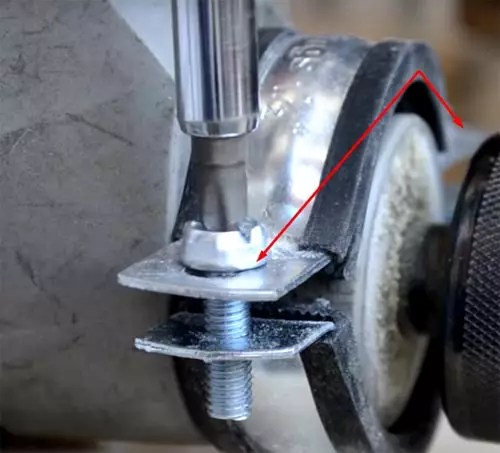 | All screws of the clamps are pulled thoroughly. The reliability of fastening, and hence the final result, depends on this. |
 | In the chuck of a fixed electric drill, we install a workpiece with a drill driven into it and stretch the clamps with a special key. |
 | We press on the reverse side with the driven center for reliable two-sided fixation. One-sided fastening of the workpiece will not work. All that can be achieved with this is to break the bearings of the drill. |
 | Thoroughly tighten the fixing nuts. Now the equipment is ready to work. |
 | We turn on the drill at maximum speed. The power button is fixed with a button on the side of the handle. Now the workpiece can be given the desired look with a chisel and a file. |
 | Here we have such a neat pen. If you need to grind a metal cylinder, it should be clamped into a chuck, and drill a small hole on the reverse side of the driven center mount, lubricating it with grease or lithol. The rest of the steps are similar. |
Drill units are easily upgraded. For example, the bed on which the electric drill is attached is made movable, and the part is statically fixed. Then, by installing different cutters instead of a drill, cone-shaped or other holes are made. A wheel with sandpaper will allow you to evenly sand the surface.
As for the installation of the CNC (numerical program control), it will not be possible to do such work on your own. It involves the replacement of components and mechanisms of the lathe.
Good to know! Working on a CNC machine is no easier than working on a mechanical one. The turner also needs to know everything about the speed of rotation, reading drawings and projects, materials of cutters for various metals.

As in the operation of each equipment, various sometimes unpleasant situations arise during the operation of home-made lathes. Powerful motor for working with large metal parts, gives sensitive vibrations. This leads to uneven processing of the workpiece - marriage. This is treated by setting the centers (leading and driven) on one axis, or using a cam mechanism (with one leading center).
It is not recommended to install a collector motor as an electric drive - it is better to use an asynchronous one. It eliminates the disadvantage of unplanned over-revving that can cause the workpiece to fly out of the clamps, causing personal injury or property damage.
We offer you to see a few photos of lathes made by the hands of ordinary home craftsmen.

In order to make it easier for the reader to understand the algorithm for manufacturing such units, below is a video of making a lathe with your own hands:
The main thing, as in any business, is attentiveness and accuracy. This applies to every action, from the strength of the clamping of the workpiece to the slightest movement of the cutter. There are special requirements for clothing. It is forbidden to work in loose-fitting overalls, with dangling sleeves or the bottom of the jacket. If the clothes are just like that, you should fix the jacket on the sleeves and on the bottom with an elastic band. Remember, if the sleeve is wound around a rotating workpiece, you can be left without a hand.

It is important to monitor the condition of the wiring. At the slightest smell of burnt insulation, you need to turn off the voltage and find the source. Cutters are carefully inspected for cracks before starting work. If one is found, the use of the tool is prohibited.
Very important! Under no circumstances should you approach the machine while intoxicated. Even a small dose of alcohol or a hangover reduces attentiveness. According to statistics, 70% of people left without limbs as a result of an injury at work were intoxicated or suffered from a hangover.
After each use of the machine, it must be swept clean so that no dust and chips remain. After that, all rotating parts are lubricated.

Before turning on the unit, it is visually inspected for violations of the insulation of the electrical wiring, normal rotation of the bearings. A short-term inclusion without a clamped workpiece is mandatory - “idle”.
The cost of such factory-made units is quite high. Consider the prices for some models presented on the Russian market as of January 2018:
| brand, model | Workpiece diameter (max), mm | Rotation speed, rpm | Unit weight, kg | Cost, rub. |
| 110 | 400÷3600 | 13 | 28 000 |
| 180 | 100÷2500 | 33 | 48 000 |
| 300 | 50÷2500 | 38 | 53 000 |
| 300 | 5000 | 6.3 | 10 100 |
| 250 | 500÷3500 | 27 | 14 000 |

If the home master has the education of a turner or at least similar skills, a lathe on the farm will be useful. It will help save on the purchase of some parts for mechanical devices, polishing or even painting. It is also made for stools or tables. As it became clear from the article, it is not so difficult to make such a unit with your own hands. You just need to be attentive to the schemes and follow certain rules.
Individual entrepreneur details in the contract include mandatory and additional information....

Storage of cash in institutions and at individual entrepreneurs is carried out at the cash desk. For analysis...

The problem that users of 1C: Pіdpriёmstvo encounter is “Error: Field ...