INSTRUCTIONS AND PROPHECIES OF THE Blessed MOTHER ALIPIA GOLOSEEVSKY, Kyiv...


For installation of "earth" in residential and industrial premises are used different types wires and principles of installation of protective structures. Grounding systems for electrical installations TN (subtypes TN S, TN C S), TT and IT can be used both for a private house and for an apartment.
The designation of all systems is deciphered as follows:
Classification of grounding systems and their description for grounding taps:
Also, modern GOST parameters introduced such a thing as a zero grounding conductor (used in systems with voltages up to 1000 V). It can be N - just zero, PE - earth, PEN - earth combined with zero.
The principle of operation of each specified system is different, therefore, the PUE does not allow the use of certain types protective earth before checking compliance with the requirements of certain electrical networks.
Consider a description of the operation and diagrams of each of the grounding systems used.
TN is a system in which the neutral wire is solidly grounded, and all other electrical outlets are connected to it. The features of this scheme are that for its implementation, a special reactor is installed near the transformer, which extinguishes the arc that appears in the wiring.
Photo - TN-C This system has two varieties: TN-C and TN-CS. TN-C is characterized by the fact that one combined tap is used to protect the power supply system, combining neutral and earth. This conductor is most often used in residential areas, industrial areas, etc. It has its own advantages and disadvantages:
Compared to it, TN-CS is more secure for domestic use. It consists of two cables: ground and zero. If you are arranging wiring in a new house, we recommend that you pay attention to just such a separate option, it is ideal for a new housing stock.
 Photo - TN-S
 It stretches from the very transformer substation where it is directly grounded. Because of this, you may encounter a number of problems during installation. Besides technical design and PUE requirements require the use of a three-core or five-core wire for its implementation.
To simplify the installation of the land, they came up with a system that combines the advantages and simplifies the disadvantages of the previous two. This is TN-C-S. Here, as in the TNC, there is a neutral wire, which contributes to an increase in leakage resistance, but, like the TNS, it is separate. Due to this, it provides an instant response of the RCD in an emergency.
 Photo - TN-C-S
 It does not require the use of expensive five-core wire and can be mounted in any buildings and for various conductor cross-sections. At the same time, it should be noted that grounding is carried out through risers in the entrance, so you must first obtain permission from the power supply company. Also, the disadvantages include the fact that if the ground cable breaks, then the open outlets of the risers can be under high voltage.
The TT solid grounding and lightning protection system circuit is solidly grounded and fully isolated. It uses special neutral adapters to connect open outlets of electrical installations or communications. Its principle of operation is very simple, but it is not suitable for a house or apartment. To put it simply, a metal peg is hammered into the ground near the building, which is connected to the outlets. Equipment is connected to such a circuit. The installation of such a system is allowed only in small non-residential premises, say, in the bath, MAF and other buildings. It can also be used for lighting or local heating (greenhouses, incubators). A professional version can be seen at Zandz.
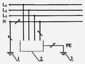 Photo - TT
 The main advantage of this rod method is its mobility. If necessary, the entire contents of this modular design is simply transferred to another place, which cannot be done with any other "land". This is very convenient when a permanent fixed system needs to be replaced, checked, inspected or repaired.
 Photo - rod
 The application of the IT system is mainly carried out by various laboratories or medical organizations. Installation is carried out by means of a neutral, which is isolated from the ground. This is sometimes used where the earth is connected by attaching a neutral cable to appliances with very high resistance. Her technical execution ensures the almost complete absence of various magnetic fields, eddy currents and other disadvantages of other grounding systems. A similar kit (Galmar and others) can be bought and used for domestic purposes, but it is quite expensive. Its cost varies from $50 to several hundred (the price depends on the length of the system).
 Photo - IT
 Video: grounding and grounding
Certain requirements are put forward for each system, they are described in the relevant GOSTs, so we will separately tell only about general features:
The most perfect, for today, grounding system "TN-S"(type of electrical network) strongly recommended for use by the PUE (Electrical Installation Rules). In Russia, a system similar to TN-C is still used (TN-C system is prohibited in new construction, in single-phase and direct current. This requirement does not apply to branches from overhead lines with voltage up to 1 kV to single-phase consumers of electricity - PUE 1.7.132).
Grounding system "TN-S"- from supply substations two different neutral wires go to the consumer: N - working zero and PE - protective zero, thereby ensuring the greatest electrical safety, both for humans and for electrical consumers.
In the event of a breakdown to the case, the leakage current flows through the grounding (grounding) conductor to the protective zero - PE, which causes a trip RCD(currents through the differential transformer to the load and back are not equal). And with a large leakage current, it works circuit breaker
In general, the "TN-S" grounding system was first developed in the 1930s and introduced on the territory of European countries, in which recent years 50 is the main scheme for protecting electricity consumers. Most likely, the same task is facing the Russian enterprises of electrical networks, since when designing new power supply development lines, it is recommended to use a five-core electrical installation for three-phase inputs and three-wire - for single-phase connection, starting from the power source and ending with the outlet of a specific subscriber. As you know, recommendations very often turn into norms and provisions of standards, but for now one of the stages of such a transition is mandatory electrical installation according to the system grounding TN-С-S, since the direct transition from TN-С to TN-S involves large capital investments and is comparable to the construction of a new hydroelectric power station.
Fig1. TN-C system

Fig2. TN-S system

Fig3. TN-C-S system
What is so remarkable about it, if it is required, albeit a gradual, but mandatory transition? To find out, let's first look at it. wiring diagram. It is completely identical with traditional system power supply, where, in addition to current-carrying lines, a neutral conductor is included, with the important difference that another neutral conductor is added to the circuit, which does not require re-grounding neither on the "N" line, nor on the "PE" line, which is carried out only on the initial power source. Thus, allowing them to separate their working and protective functions on separate power rails. That is, the working conductor "N" performs only the functions of an EMF (an electromotive force is a physical quantity that characterizes the work of external (non-potential) forces in sources of direct or alternating current. In a closed conducting circuit, the EMF is equal to the work of these forces in moving a single positive charge along the circuit), and the conductor "PE" - only protection functions, while achieving complete isolation from each other. Such a wiring diagram is especially relevant in the context of problems when there is absolutely no control over the state of protective grounded circuits, as you can see, the need for this is completely eliminated.

Now, after we figured out the electrical circuit, it becomes obvious that such a TN-S grounding system provides maximum protection for electrical equipment and the person himself. Moreover, it eliminates high-frequency pickups and other interference on consumer lines coming from some devices. Each of us must have observed a similar situation when someone used an electric razor in the next entrance, sometimes a drill or welding machine, rattling distortion appeared on the TV screen. Such a system, if not completely, then most interference, oscillatory and electromagnetic excitations that sometimes occur in electrical networks, certainly eliminates. Therefore, the TN-S grounding system is very fond of employees who work with information, telecommunications, radar or location equipment, since maximum isolation from casings and cases of other electrical devices, as well as pickups through the "ground", in other words, from interference sources.
Conventions grounding systems:
First letter is the state of the source neutral with respect to earth.
T- grounded neutral.
I- isolated neutral.
Second letter- state of exposed conductive parts relative to earth.
T- exposed conductive parts are earthed regardless of the relation to earth of the neutral of the power supply or any point of the supply network.
N- exposed conductive parts are connected to a dead-earthed neutral of the power source.
Letters after N- combination in one conductor or separation of the functions of the zero working and zero protective conductors.
S- zero working (N) and zero protective (PE) conductors are separated.
FROM- the functions of the zero protective and zero working conductors are combined in one conductor (PEN-conductor).
In the distribution electrical networks of the Russian housing stock, for several decades, the outdated TN-C grounding system has been massively replaced by a more modern (and much safer) TN-C-S. In fact, the last of them is a symbiosis of the TN-C and TN-S systems and differs from the others in such a way. design feature, as a pair "splitting" of the PEN conductor, carried out at the branching site of the general distribution network into separate ones going to consumers. As a result, 2 conductors are formed:
In this case, the power supply circuit with such a grounding system in the distribution access panel takes the following form: 
When using a single-phase power supply (and a corresponding meter installed inside the shield box), a 3-core cable goes to the internal apartment shield (respectively with phase C, protective conductor PE and working neutral conductor N) - indicated in the diagram by red, blue and light green lines.
In the presence of a three-phase power supply (and a meter), a 5-core cable is already used, in which a pair of wires A is added (marked yellow) and B (dark green).
Thus, unlike the "sovdepovskaya" TN-C system, TN-C-S involves the use of not outdated, but new euro sockets, which are necessarily supplied with internal ground terminals.
As for the aforementioned "splitting" of one conductor into a pair, the worker (N) still serves to perform the main function - supply to various devices power consumer. At the same time, an additional, protective PE is connected to the housings of electrical appliances and household appliances(dishwashers and washing machines, electric stoves, microwave ovens etc.).
However, where exactly to share the common PE-N conductor? This question is not idle, and therefore requires a separate careful consideration with explanations.
At the entrance of the public power grid from the street to large buildings, an ASU (input switchgear) must be installed. Structurally, it looks something like this:
As can be seen from the figure, the standard ASU (in this case- 0.4 kV) contains a combination of:
At the same time, the general clear picture when using the TN-C-S system, it will take the following form: 
And since the conductor will be divided inside the ASU, schematically this will be done as shown in the photo below: 
For separation, you will need to use two corresponding tires:
The input cable (with a common conductor) will be fed to the ground bus. The same, in turn, will be connected to the upper busbar by a rigid jumper (if possible, made of the same material and approximately the same width as both busbars, or made in the form of a wire with a cross section equal to the PEN conductor).
Then the connection diagram will take the following appearance: 
In addition, the lower bus, PE, will need to be grounded again - in other words, brought to the ground loop of the building itself.
Important! The electrical dimensional parameters of the conductor going to the place of its separation may be different, but in no case should the lower limit norm fall in the cross section: for copper wire– not less than 10 mm2; for aluminum - not less than 10 mm2.
Moreover, all of the above are not just recommendations, but direct requirements of the PUE.
It should be noted that the TN-C-S system in the power grids of Russia today is not only the most common, but also, perhaps, the most promising. Thanks to the use of RCDs (devices that provide automatic protective shutdown), its level of safety is much higher than still in many of the remaining (mainly in Khrushchev and Brezhnevka) old TN-C systems, although lower than that of modern TN-S.
However, it is precisely the ability to easily and without unnecessary financial and time costs to implement a symbiosis of outdated and advanced grounding systems into a single whole and allows us to classify it as optimal for this moment for our state.
In fact, it is only one - and it consists in the event that the PEN conductor breaks due to any force majeure circumstances, and the housings of electrical appliances are energized.
Despite the "lack of perfection" of the TN-C-S system, the transition in buildings with completely outdated grounding of the TN-C type to it is more than recommended.
Similar materials.
Standard Standard PUE 1.7, EN60950, IEC60364
Load power supply schemes TNC, TNCS, TNS, TT, IT
TNC– Neutral and PE (“earth”) are combined together everywhere in the system in a single PEN bus.
Neutral and PE (protected earth conductor) are combined throughout the system.
TNS– The neutral is connected to the transformer earth, but is not connected to earth (PE) anywhere else in the system. PE comes to the site from the transformer separately and can be connected to local ground.
Neutral is earthed at the transformer but is not bonded to earth or the PE elsewhere. PE is carried to the site from the transformer and bonded to site earth.
TNCS– The PEN bus, which is common at the beginning, is then split into 2 separate conductors: N (neutral) and PE (protected earth bus). The US standard is a variation of this one. The neutral is earthed at the transformer.
TNCS splits the combined PEN into a separate neutral and PE at service entry (U.S. practice is a variation of this). The neutral is earthed at the transformer.
TT– The neutral is earthed at the transformer. Local Earth - PE (consumer object) is not connected to neutral. There are no connections between transformer earth and consumer earth (PE).
Neutral is earthed at the transformer. The PE originates at site but is not bonded to the neutral. There is no interconnection between PE and transformer earth.
IT– Transformer neutral is not earthed (or earthed through a high impedance resistor).
The transformer is unearthed (or earthed through high impedance). The PE originates at site but is not bonded to a service conductor; no conductor in this system is designated as ‘neutral’ (standard IT system).
Types of IT systems:
The neutral on the consumer is also not grounded (or grounded through a high impedance resistor).
For both cases, variations are possible:
The main requirement of the IT system is an ungrounded or impedance-grounded transformer neutral point.
 |
||
 |
 |
|
 |
||
Terms / abbreviations:
Three grounding systems have been given official status through a standard (IEC 60364) which is subdivided into big number national standards.
Basic principles of the TN scheme:
Existing TN scheme options:
The TNS system cannot exist before the TNC system.
General remarks:
In a TNC system with circuit breakers, insulation failure is dangerous. The destruction of the insulation, that is, the short circuit of the phase conductor to the "Earth", causes an increase in the fault current to the maximum value, limited by the circuit breakers in the circuit.
Such protection in many cases is sufficient to protect the load itself, but is not complete, for example, if the insulation is not completely destroyed and the current of the “Earth” phase is insufficient to trip the circuit breaker. However, this can lead to a fire or dangerous electric shock to a person, and the circuit breaker will not work (it will not provide a protective shutdown of the emergency section of the circuit).
The system has the lowest level of security, since the RCD cannot be correctly installed.
Despite the danger, the system continues to be used in Russia, incl. at state enterprises. In Russia, it is currently being replaced by the TNS system.
Detailed remarks:
 |
Fig.1. Insulation failure in the TNC system
Possible options:
General remarks:
The maximum degree of safety can be achieved by installing an RCD. The system is the most widespread in the world. In Russia, introduced as a standard.
The degree of security of TNS is higher than TNC for the following reasons (P1, P2):
Detailed remarks:
 |
Fig.2. Insulation failure in the TNS system
Possible options:
General remarks:
In a TNS system with circuit breakers, insulation failure is dangerous. The destruction of the insulation, that is, the short circuit of the phase conductor to the "Earth", causes an increase in the fault current to the maximum value, limited by the circuit breakers in the circuit.
Such protection is in many cases sufficient to protect the load itself, but is not complete, for example, if the insulation is not completely destroyed and the phase-Earth current is insufficient to trip the circuit breaker. However, this current may be sufficient to start a fire or to cause a dangerous electric shock to a person, and the circuit breaker will not work (it will not provide a protective shutdown of the emergency section of the circuit).
The protection system has an average level of safety, since by installing an RCD you can achieve a sufficiently high degree of safety, but there remains the problem of poor-quality grounding due to the use of the combined PEN bus.
Used quite often in Russia. In Russia, it is currently being replaced by the TNS system.
Detailed remarks:
 |
Fig.3. Insulation fault in TNCS system
Possible options:
Basic principles of the TT scheme:
General remarks:
The degree of safety depends on the resistance between the "Earth" of the transformer substation and the "Earth" of the consumer. If this resistance is low, the safety is the same as in TNS with RCD. If this resistance is high, the safety of the system is reduced, as the RCD may not trip.
RCD installation is common in the TT system. This system rarely used in Russia.
Detailed remarks:
 |
Fig.4. Insulation failure in TT system
Possible options:
A typical CT with RCD is shown. The breakdown current (violation) of the insulation of the phase wires and the neutral wire is limited by the resistance (impedance) of the section between the "Ground" of the transformer and the "Ground" of the consumer.
Protection is provided by the Residual Current Device (RCD): the damaged block / section is switched off by the RCD as soon as the current threshold ΔI of the RCD placed in front of this block / section is exceeded by the leakage / insulation breakdown current (to ground) IL:
IL > ΔI
IL = UL / RL - breakdown / leakage current / leakage
The condition for reliable operation of the RCD:
R (CD)<< 220 В / ΔI; для УЗО с ΔI =30мА: R (CD) << 7кОм.
R (AB) \u003d RL - resistance of the damaged section (between the point of the current-carrying conductor from which leakage occurred to the "ground" and "Earth").
U (AB) \u003d UL - the potential difference between the point of the current-carrying conductor (from which the leakage to the "ground" occurred) and "Earth" (breakdown voltage).
R (CD) - resistance between the "Earth" of the TS transformer and the "Earth" of the consumer.
If R (CD) is small (normal), then in the event of insulation failure, the RCD trip will ensure the safe shutdown of the emergency section and indicate that this place needs to be repaired.
If R (CD) is large (not normal) and the RCD will not work, then the first violation of the insulation will not lead to an electric shock, but the absence of a triggered RCD will not allow detecting an accident and making timely repairs, and the second breakdown will lead to an accident.
Basic principles of the IT scheme:
Detailed remarks:
Fig.5b. Double fault / insulation failure in IT systems
I L1 \u003d U Ф / R lines
U L1 = R L1 * I L1
The first insulation violation is not dangerous in IT! That is, a person can safely touch both the phase and the "Earth" in IT.
R L1 - resistance of the damaged section (between the point of the current-carrying conductor from which the leakage to the ground and the "Earth" occurred.
U L1 - potential difference between the point of the current-carrying conductor (from which the leakage to the ground occurred) and "Earth" (breakdown voltage).
U f - phase voltage of the transformer
I L1 - breakdown / leakage current / leakage.
If a second insulation fault occurs on another phase conductor, while the first violation has not yet been eliminated (see Fig. 5b), the contact potential difference of the second violation point (breakdown voltage) is equal to U L2 = √3 * U Ф -U L1 can be large and dangerous.
With low resistances of the first and second damaged sections (R L1 , R L2 ), a significant leakage current can flow through the conductor connecting the "grounds" of the first and second damaged sections (load cases):
I L1 = I L2 = √3*U Ф / (R L1 + R L2)
The second insulation violation is dangerous in IT!
The load cases acquire potentials due to this current. Thus, if a short circuit in section 1 is not dangerous, then a subsequent short circuit in section 2 is just as dangerous as in TN systems. Therefore, an RCD is needed.
Designations:
The combined use of current protection circuit breakers and RCDs provide the necessary protection in these cases. In this case, in terms of safety, the IT system is comparable to TNS with RCD, that is, the operation of the RCD (the emergency section is turned off) indicates that the first insulation violation has occurred and allows it to be eliminated in a timely manner.
For reliable operation of the RCD, the installation of a forced resistance Z N (Neutral-“Earth”) is required, usually not more than 1500 ohms. Without this resistance, the first breakdown cannot be detected (and eliminated in a timely manner) if there are no other devices in the system (except for RCDs and current circuit breakers - see below).
In addition to these possibilities, only the IT system allows you to further increase security.
You can further increase the degree of security by installing a PMI / PIM (Permanent Insulation Monitoring / Insulation Sensor). PMI is a high-resistance ammeter (or voltmeter connected in parallel Z N ), included in the same way as Z N between the Neutral and "Earth" of the TS.
PMI allows:
Unlike other systems (TN, TT), this allows you to detect the first insulation violation, but not turn off the emergency section (since in IT the first insulation violation is not dangerous), but to complete the work on it, and only after it is completed, perform a regular disconnection and repair of insulation. This is especially important, for example, for hospitals and other places where it is important not so much to automatically “cut off” the emergency circuit in a timely manner, but to eliminate all malfunctions in advance and exclude the possibility of a sudden uncontrolled automatic disconnection of the circuits. Therefore, the IT system has been introduced in many countries as a standard for hospitals, structures connected with conductive media (water, earth, etc.), such as ships, subways and other places requiring increased security.
Thus, enhanced security of an IT system refers to the ability to safely detect and repair insulation faults on all conductors in the system.
In an IT system, the installation of current circuit breakers is mandatory. RCDs are installed depending on the characteristics of the loads and the applied Z N and PMI.
In addition, the PMI protective circuits themselves are additionally protected, for example, at the transformer substations using a surge arrester or a voltage surge protection unit (surge limiter, surge suppresor).
All of the above information relates to the protection of the user, who has access only to insulated wires and electrical equipment in a protective enclosure.
Please remember that deeper penetration into electrical equipment can be life-threatening, even with the safest grounding systems, when using circuit breakers, RCDs, insulation sensors, etc.
Examples of severe danger to humans:
Example 1
Installed: Any grounding system. Any protection devices in AC circuits. UPS 100 kVA - batteries in the battery cabinet are always energized (including when the UPS is turned off) and dangerous.
ATTENTION! HIGH DC VOLTAGE!
Example 2
IT system. There is an automatic. There is an RCD. There is an isolation sensor. There is an insulated mat. There is any device, for example, an electric motor, a stabilizer, a 100 kVA UPS. Human contact (simultaneous) between phase and neutral, or between two phases on the terminal strip (or corresponding broken wires) of this device is dangerous
ATTENTION! HIGH AC VOLTAGE!
(The RCD will not work if the person is on an insulating mat!)
Example 3
Also, a person’s defeat can happen without touching live conductors at all, for example, a wrench dropped on the terminals of a 100 Ah battery assembly can burn out like a fuse with a dangerous light flash and hitting the surrounding area with metal splashes.
To ensure complete security, 4 additional conditions are necessary:
Classification of grounding systems for electrical installations and modernization of apartment wiring. Application experience.
To properly repair or upgrade wiring, you need to know exactly which grounding system is used at the facility. Your safety depends on it, in addition, it is important when drawing up a reconstruction project. In some cases, for example, a three-core cable is used, and in others four and five-core.
Classification grounding systems for electrical installations according to IEC
The International Electrotechnical Commission and, at its filing, the 7th edition of the PUE (electrical installation rules) distinguish 3 grounding systems and several of their subsystems.
1. TN system (TN-C, TN-S, TN-C-S subsystems);
2. TT system;
3. IT system.
TN system
The TN system is grounded neutral system, in which the open conductive parts of the electrical installation are connected to a solidly grounded neutral source using zero protective conductors.
Term solidly grounded neutral means that at the transformer substation, the neutral (zero) is connected directly to the ground loop (grounded).
The TN-C subsystem is a TN in which the zero protective and zero working conductors are combined throughout its entire length, i.e. .
TN-S is a system in which the zero protective and zero working conductors are separated throughout. This is the safest, but also the most expensive system.
The TN-C-S subsystem is an intermediate option. In it, the zero protective and zero working conductors are combined in some part of it. Usually this is the main shield of the building (protective grounding is supplemented by protective grounding). Further throughout the building, these conductors are separated. This system is optimal in terms of price-quality ratio.
IT system
This is a system in which the zero of the source is isolated from the ground, or grounded through devices with high resistance, and the open conductive parts of the electrical installation are grounded using grounding devices. Now the IT system is almost never used.
TT system
This is a system in which the zero of the source is grounded, and the open conductive parts of the electrical installation are grounded using a grounding device that is electrically independent of the grounded zero source. In other words, it uses its own ground loop on the object, which is in no way connected with zero.
Today, this system is the main one for mobile structures, such as change houses, caravans, etc. Note that it is more difficult to coordinate the use of such a system than TN. It becomes mandatory, high-quality grounding is required (4 ohms for 380 V), there are features in the selection.
What system of grounding electrical installations to use and how to upgrade?!
Based on the foregoing, it is best to use a TN grounding system.
The TN-C system has been used in the past and cannot be recommended for new housing.
The TN-S system is good for everyone, but it is expensive and rarely used so far. The best option so far is the TN-C-S system.
Let us now dwell on the typical difficulties and mistakes encountered in the modernization of grounding systems.
1. If we consider a private house in which the wiring has already been made with a three-wire wire (phase, zero, ground), then replacing TN-C with TN-C-S is quite simple. It is only necessary to make high-quality grounding, connect it to the introductory electrical panel and connect the PE wires of sockets and lamps to the connection point of zero and earth (N and PE) (usually it is a yellow-green wire).
2. In an apartment or apartment building that is not equipped with a ground loop, this cannot be done. Wiring, of course, is also better to do with a three-wire cable, but you don’t need to connect it, not in sockets (lamps).
The reason is that if you connect this wire to zero wiring (there is nowhere else to connect it, except perhaps the battery, which is prohibited), then due to the voltage drop in the neutral wire from the currents of the switched on loads, your equipment cases will be energized relative to ground ( batteries, pipes, etc.).
3. During operation, there are other incidents, for example, after eliminating the accident, electricians mix up the neutral and phase wires. Neighbors who do not have a neutral wire on the equipment case are not in danger, and your case is at phase potential!
4. It is not uncommon for the input cable to burn out zero, which occurs when the phases are unbalanced, in this case there will also be a dangerous potential on the case.
Based on the foregoing, it follows the need to use . These are devices that turn off the 220/380 V network when insignificant (but sensitive!) Currents of 10-30 mA flow through the human body. The disadvantage of these devices is that they will work with any leakage currents, for example, when neighbors spilled you. It gets very difficult.
So, when repairing wiring, use the TN-C-S grounding system. Lay wiring with colored core insulation (for example, VVG NG).
If the house does not have a ground loop, do not connect the ground wire to zero. For wiring in rooms where there is a lot of moisture, use.
INSTRUCTIONS AND PROPHECIES OF THE Blessed MOTHER ALIPIA GOLOSEEVSKY, Kyiv...

Eufillin dropper in ampoules is used to treat pathologies that ...

Among all ointments for the treatment and prevention of joint diseases, the most ...