


 The fundamental electrical circuits of various monitors: both old kinescopic and modern LCD
"The woman is created for a man, not a man for a woman" - such a postulate ...


Electrical circuits for beginners, for lovers and professionals
Welcome to the Radioshem Section! This is a separate section of the radio amateurs website which was created specifically for those who are friends with the soldering iron, you used to do everything yourself with your own hands and is dedicated exclusively by electrical schemes.
Here you will find fundamental schemes of various themes like la self-assembly novice radio amateursAnd for more experienced radio amateurs, for those who the word of the radio has long been not just a hobby and profession.
In addition to the schemes for self-assembly, we have a large enough (and constantly updated!) Base of electrical circuits of various industrial electronics and household equipment, monitors, magnetol, amplifiers, measuring instruments, washing machines, microwaves, and so on.
Especially for repair workers, our site has a section "Datasheets", where you can find reference information to various radio elements.
And if you need any scheme and there is a desire for it download, then we have everything here free, without registration, without SMS, without file sharing And other surprises
If there are questions or did not find what they were looking for, go to our forum, think together !!
To facilitate the search for the necessary information, the section is divided into categories
|
Schemes for beginners In this section collected simple schemes for beginner radio amateurs. |
Light and music
light devices x Effects: Flashing, color music, stroboscopes, garlands switching machines and so on. Of course, all schemes can be assembled independently materials in category |
Power sources schemes
Any radio electronic instrument needs food. It is the sources of nutrition and a given category materials in category |
|
Electronics in life In this category, diagrams of devices for domestic use are presented: rodent repellers, various alarms, ionizers and so on ... |
Antennas and radio receivers Antennas (including homemade), antenna components as well as schemes of radio receivers for self-assembly |
Spy things
In this section, there are schemes of various "spyware" radio-inlets, silencers and phone listeners, radio-party detectors |
|
Auto motor electronics
Circuit diagrams of various auxiliary devices to cars: Chargers, turn signs, headlights and so on |
Measuring instruments
Electrical concepts of measuring instruments: both self-made and industrial production materials in category |
Domestic technology 20th century
A selection of electrical concepts of household radio equipment issued in the USSR materials in category |
|
LCD TV Schemes (LCD)
Electrical LCD TV Schemes (LCD) materials in category |
Schemes programmen
Schemes of various programmers materials in category |
Audio equipment
Schemes of devices associated with sound: Transistor amplifiers and on chips, pre-and lamp, Sound conversion devices materials in category |
|
Monitor schemes
materials in category |
Schemes of automagnetol and other auto-audio
Collection of automotive audio schemes: car radio, amps and automotive televisions |
Nowadays, there is a huge selection of radio electronics tools and appliances: soldering stations, stabilized laboratory power supplies, engraving sets (for drilling boards and processing structural materials), tool for stripping and processing wires and cables and so on. And all this equipment costs a lot of money. There is a reasonable question - can a beginner radio amateur to buy all this arsenal of equipment? The answer is obvious, especially for some people who are fond of electronics on the occasion (for a single manufacturer of some useful devices for household purposes), the purchase of such a number of tools is required. The way out of the created position is pretty simple - make the necessary tool with your own hands. These homemade will serve temporary (and for someone and constant) alternative to the factory equipment.
So, proceed. The basis of our device is a network reduction transformer from any radio-electronic device service (TV, tape recorder, stationary radio, etc.). The network cord, fuse block and power switch can also be useful.
Next, you need to provide our power supply unit with an adjustable voltage stabilizer. Since the design is designed to repeat beginner radio amateurs, the most rational, in my opinion, will be the use of an integral stabilizer on a LM317T type chip (K142EN12A). Based on this chip, we collect an adjustable voltage stabilizer from 1.2 to 30 volts with a complete load current up to 1.5 amps and protection against current overload and exceeding temperature. The schematic diagram of the stabilizer is represented in the figure.

You can collect a scheme of the stabilizer in a piece of non-ruffled glass-shake (or electrocarter) by mounting or on a dumping board - the scheme is so simple that it does not even require a circuit board.

At the output of the stabilizer, you can connect (in parallel with the outputs) of the voltmeter, to control and adjust the output voltage, and (sequentially with the plus output) of the milliammeter, to control the streamliness of the radio ammonion connected to the stabilizer.

Another necessary thing in the arsenal is a novice radio amateur thing - microelectrodrod. As you know, in the arsenal of any (beginner or magic experience) of the homemade serviceman exists "warehouse" from everybody or malfunctioning equipment. Well, if on such a "warehouse" there is a children's machine with an electric drive, micromotor from which will serve as an electric motor for our microdel. It is only necessary to measure the diameter of the engine shaft and in the nearest radio market to purchase a cartridge with a set of collet clamps (under the drill of different diameter) for this micromotor. The resulting microdel can be connected to our power supply. By regulating the voltage, you can adjust the number of drill revolutions.

The next needed thing is a low-voltage soldering iron with a galvanic interchange from the network (for soldering of field transistors and chips that are afraid of a static discharge). There are low-voltage soldering iron on sale at 6, 12, 24, 48 volts, and if the transformer, which we chose for our product from the old tube TV, can be considered that we are big lucky - we have a ready-made winding for the nutritional of low-voltage electrician (you should use The slot windings (6 volts) of the transformer for powering the soldering iron). The use of a transformer from a lamp TV gives another plus to our scheme - we can equip our device as a tool to stripping the ends of the wire.

The basis of this device is two contact pads, between which the nichrome wire is fixed and the button, with normally open contacts. Technical design of this device can be seen from the picture. It connects everything to the same transformer slotting. When you click on the button, the nichrome is heated (everything will probably remember what an exignment is) and burns the insulation of the wire in the right place.

The housing for this power supply can be found ready or collect yourself. If you make it from metal and provide ventilation holes only from below and on the sides, then you can position the racks for the soldering iron and the stripping tool. Switching the entire farm can be carried out by applying a batch switch, a system of togglers or connectors - there is no limits here for fancy.

However, this block can be upgraded under its needs - supplement, for example, a charger for batteries or electric spacing engraver, etc. This device served me for many years and is still served (the truth is now in the country) for the manufacture and inspection of various radio-electronic and electrical homemade. The author is an electroded.
Below are simple light-sound circuits, mainly assembled on the basis of multivibrators for beginner radio amateurs. In all schemes, the simplest element base is used, the complex commissioning is not required and it is allowed to replace the elements to similar in wide limits.
Electronic Duck
A toy duck can be provided with a simple scheme of the "Kryakanya" simulator on two transistors. The scheme is a classic multivibrator on two transistors, in one shoulder of which an acoustic capset is turned on, and two LEDs serve as a load that can be inserted into the eyes of the toy. Both of these loads work alternately - the sound is heard, the LEDs break out - the duck eyes. As the SA1 power switch, you can apply a gear sensor (you can take from the SMC-1 sensors, the SMK-3, etc., used in the system of security alarms as the door opening sensors). When the magnet is raised to therch, its contacts are closed and the scheme starts working. This can occur when the toy is tilted to the hidden magnet or the cause of a peculiar "magic wand" with a magnet.
The transistors in the diagram can be any PNP type, small or medium power, for example MP39 - MP42 (old type), CT 209, KT502, KT814, with a gain of more than 50. You can use the transistors of the NPN structure, for example KT315, CT 342, KT503 But then you need to change the polarity of the power, the inclusion of LEDs and the polar capacitor C1. As an acoustic emitter, the BF1 can use Capsul type TM-2 or a small-sized speaker. The setting of the scheme is reduced to the recruitment of the resistor R1 to obtain the characteristic sound of the rush.
Metal Ball Sound
The scheme simplifies such a sound quite accurately, as the C1 condenser discharges, the volume of "strikes" decreases, and the pauses are reduced between them. At the end, the characteristic metal rattle will be heard, after which the sound will stop.
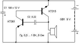
Transistors can be replaced with similar as in the previous scheme.
The total duration of the sound depends on C1 tank, and C2 determines the duration of the pause between "blows". Sometimes for more believable sound it is useful to choose the VT1 transistor, since the operation of the simulator depends on its initial current of the collector and the gain coefficient (H21E).
Motor sound imitator
It is possible, for example, to voice the radio-controlled or other model of the mobile device.
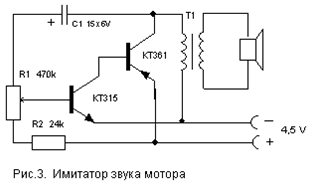
Options for replacing transistors and dynamics - as in previous schemes. Transformer T1 - the output from any small-sized radio (through it the speakers also connected).
There are many schemes of imitation of sounds of birds singing, animal voices, beeps of steam locomotive, etc. The scheme proposed below is collected in just one digital chip K176L7 (K561 LA7, 564L7) and allows you to imitate many different sounds depending on the resistance value connected to the input contacts X1.

It should be noted that the microcircuit here works "without meals", that is, on its positive output (leg 14) does not supply voltage. Although in fact the nutrition of the chip is still carried out, but it only occurs when the sensor resistance is connected to x1 contacts. Each of the eight chip inputs is connected to the inner power supply through diodes protecting from static electricity or incorrect connection. Through these internal diodes and the microcircuit is powered by the presence of positive feedback on power through the input sensor resistor.
The scheme is two multivibrators. The first (on the elements of DD1.1, DD1.2) immediately begins to produce rectangular pulses with a frequency of 1 ... 3 Hz, and the second (DD1.3, DD1.4) is included in the work when the level of logical will be switched to the output 8 from the first multivibrator. one". It produces tonal impulses with a frequency of 200 ... 2000 Hz. From the output of the second multivibrator, the pulses are fed to the power amplifier (transistor VT1) and the industrial sound is heard from the dynamic head.
If now to the input jacks x1, connect an alternating resistor to resistance up to 100 kΩ, then there is feedback on the power supply and it transforms a monotonous intermittent sound. By moving the engine of this resistor and changing the resistance, you can achieve sound, reminiscent of nightingale, chirping sparrow, duck chaining, frog cooking, etc.
Details
The transistor can be replaced by KT3107L, CT361G. But in this case, it is necessary to put R4 with a resistance of 3.3 kΩ, otherwise the sound volume decreases. Capacitors and resistors - any types with rates close to the specified in the diagram. It should be borne in mind that in the chips of the K176 series of early editions there are no above-mentioned protective diodes and such nontrapers will not work in this scheme! Check for internal diodes easily - simply measure the resistance tester between the output 14 of the chip ("+" power supply) and its input outputs (or at least one of the inputs). As with the testing of diodes, the resistance in one direction should be low, in the other - high.
The power switch in this scheme can not be applied, since in resting mode the device consumes current less than 1 μA, which is significantly less than even the current self-discharge of any battery!
Adjustment
The correctly assembled simulator does not require any adjustment. To change the sound tonality, you can select C2 capacitor from 300 to 3000 PF and resistors R2, R3 from 50 to 470 kΩ.
Lantern-Migalka
The frequency of flashing lamps can be adjusted by the selection of elements R1, R2, C1. The lamp can be from the flashlight or automotive 12 V. Depending on this, you need to select the supply voltage of the circuit (from 6 to 12 V) and the power of the switch transistor VT3.
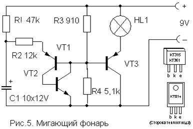
TRANSISTORS VT1, VT2 - any low-power relevant structure (CT312, KT315, KT342, CT 503 (N-P - N) and KT361, KT645, KT502 (P-N-P), and VT3 - medium or high power (CT814, KT816, KT818).
A simple device for listening to the sound of TV - gear to headphones. Does not require any nutrition and allows you to freely move within the room.

The L1 coil is a "loop" of 5 ... 6 turns of the wire PEV (PAL) -0.3 ... 0.5 mm, laid around the perimeter of the room. It connects parallel to the television dynamics through the SA1 switch as shown in the figure. For normal operation of the device, the output power of the TV channel of the TV should be within 2 ... 4 W, and the loop resistance is 4 ... 8 ohms. The wire can be paved under the plinth or in the cable channel, and it is necessary to place it as possible not closer to 50 cm from the wires of 220 V to reduce alternating voltage.

The L2 coil is wound on a frame of dense cardboard or plastic in the form of a ring with a diameter of 15 ... 18 cm, which serves as a heap. It contains 500 ... 800 turns of the PEV wire (PAL) 0.1 ... 0.15 mm fixed with glue or tape. To the conversion conclusions, a sequentially miniature volume regulator R and a headset (high-aligned, for example, tone-2) are connected.
Shutdown automatic lighting
This automaton differs from many schemes is distinguished by extreme simplicity and reliability and does not need a detailed description. It allows you to enable illumination or any electrical appliance on a predetermined short time, and then automatically turns off it.

To turn on the load, press the SA1 switch without fixation is sufficiently briefly. In this case, the condenser has time to charge and opens the transistor that controls the switching on the relay. The inclusion time is determined by the capacitance of the capacitor C and the value indicated in the scheme (4700 MF) is about 4 minutes. An increase in the time of the included state is achieved by connecting additional capacitors parallel to C.
The transistor can be any N-P-N of the type of medium power or even low-power, type Kt315. It depends on the operating current of the relay used, which can also be any other on the voltage of triggering 6-12 V and capable of switching the load of the power you need. You can use the P-N-P transistors of the type, but it will be necessary to change the polarity of the supply voltage and the switching on Conductor S. Resistor R also affects small limits for the response time and may be a denomination of 15 ... 47 kΩ depending on the type of transistor.
| Designation | A type | Nominal | number | Note | Score | My notebook | |
|---|---|---|---|---|---|---|---|
| Electronic Duck | |||||||
| VT1, VT2. | Bipolar transistor | Kt361b | 2 | MP39-MP42, kt209, kt502, kt814 | In notebook | ||
| HL1, HL2. | Light-emitting diode | Al307b | 2 | In notebook | |||
| C1. | 100mkf 10v. | 1 | In notebook | ||||
| C2. | Capacitor | 0.1 MKF. | 1 | In notebook | |||
| R1, R2. | Resistor | 100 com | 2 | In notebook | |||
| R3 | Resistor | 620 Oh. | 1 | In notebook | |||
| BF1 | Acoustic emitter | TM2. | 1 | In notebook | |||
| SA1 | Germ | 1 | In notebook | ||||
| GB1 | Battery | 4.5-9V. | 1 | In notebook | |||
| Sound imitator jumping metal ball | |||||||
| Bipolar transistor | Kt361b | 1 | In notebook | ||||
| Bipolar transistor | Kt315b | 1 | In notebook | ||||
| C1. | Electrolytic condenser | 100mkf 12V. | 1 | In notebook | |||
| C2. | Capacitor | 0.22 MKF. | 1 | In notebook | |||
| Dynamic head | GD 0.5 ... 1Vatt 8 ohms | 1 | In notebook | ||||
| GB1 | Battery | 9 Volts. | 1 | In notebook | |||
| Motor sound imitator | |||||||
| Bipolar transistor | Kt315b | 1 | In notebook | ||||
| Bipolar transistor | Kt361b | 1 | In notebook | ||||
| C1. | Electrolytic condenser | 15MKF 6V. | 1 | In notebook | |||
| R1 | Variable resistor | 470 com | 1 | In notebook | |||
| R2. | Resistor | 24 com | 1 | In notebook | |||
| T1. | Transformer | 1 | From any small-sized radio | In notebook | |||
| Universal imitator sounds | |||||||
| DD1. | Chip | K176L7. | 1 | K561L7, 564L7 | In notebook | ||
| Bipolar transistor | Kt3107k. | 1 | Kt3107l, kt361g | In notebook | |||
| C1. | Capacitor | 1 μF | 1 | In notebook | |||
| C2. | Capacitor | 1000 PF | 1 | In notebook | |||
| R1-R3 | Resistor | 330 com | 1 | In notebook | |||
| R4. | Resistor | 10 com | 1 | In notebook | |||
| Dynamic head | GD 0.1 ... 0.5Vatt 8 ohm | 1 | In notebook | ||||
| GB1 | Battery | 4.5-9V. | 1 | In notebook | |||
| Lantern-Migalka | |||||||
| VT1, VT2. | Bipolar transistor | ||||||
So. Life has developed so that I have a house in a village with gas heating. There is no live there. The house is used as a cottage. A couple of winters stupidly left the boiler with the minimum coolant temperature.
But here two minuses.
1. Gas bills are simply astronomical.
2. If there is a need to come to the house among winter, the temperature in the house is around 12 degrees.
Therefore, I had to invent something.
Immediately clarify. Availability of Wi-Fi access point in the relay zone is required. But, I think, if you are freezing, you can put a connected mobile phone next to the sensor, and distribute the signal from the phone.
Diagram Connecting the motion sensor with your own hands

It happens that you need to install in the country, or in the house lighting which will work when driving Or a person or anyone else.
With this feature, the motion sensor is well cope with this function, which was ordered by me with AliExpress. The reference to which will be below. Connecting shine Through the motion sensor, when the person passes through its vision field, the light turns on, 1 minute is lit. And turns off again.
In this article I tell how to connect such a sensor if it does not have 3 contacts, and 4 like it.
 When you need to get 12 volts for LED tape, or even for some purposes, there is an option to make such a power supply with your own hands.

This regulator allows you to adjust smoothly variable resistor fan rotation speed.
The flow regulator circuit of the floor fan came out simplest. To get into the housing from the old Nokia phone charging. There were terminals from the usual electric socket.
Installation is quite dense, but it was due to the size of the case ..
Lighting for plants with their own hands

There is a problem in the lack of lighting plants, colors or seedlings, and the need arises artificial light for them, and here such a light we can provide on LEDs do it yourself.

It all started with the fact that after I installed houses halogen lamps on lighting. When you turn on that are not rarely burned. Sometimes even 1 light bulb per day. Therefore, I decided to make a smooth inclusion of lighting based on the brightness regulator with your own hands, and I apply a diagram of the brightness controller.
Thermostat for refrigerator do it yourself

It all started with the fact that returned from work and opening the refrigerator found warmth there. The rotation of the thermostat controller did not help - the cold did not appear. Therefore, I decided not to buy a new block, which is also rare, and make the electronic thermostat itself on attiny85. With the original thermostat, the difference is that the temperature sensor lies on the shelf, and not hidden in the wall. In addition, 2 LEDs appeared - they signal that the unit is turned on or the temperature above the upper threshold.
Soil moisture sensor with their own hands

This device can be used for automatic watering in greenhouses, floral greenhouses, flowerbeds and indoor plants. Below is a diagram for which you can make the simplest sensor (detector) of humidity (or dryness) of the soil with your own hands. When soil drying, voltage is supplied, the current force is up to 90mA, which is quite enough, turn on the relay.
It is also suitable for automatic inclusion of drip irrigation, to avoid excess moisture.
Fluorescent lamp power circuit.

Often, when eating energy-saving lamps, the power circuit burns in it, and not the lamp itself. As known, LDS. With burned downstairs, it is necessary to feed the straightened current of the network using a non-valve start-up device. In this case, the filament of the lamps are shunting the jumper and which is supplied to the high voltage to turn on the lamp. An instantaneous cold ignition of a lamp occurs, a sharp increase in the voltage on it, when starting without preheating electrodes. In this article we will look at start LDS lamps do it yourself.

Somehow suddenly, I took something and understood to buy a new keyboard for my PC. The desire of novelty will not overseas. Changed the color of the background with white on the black, and the color of the letters from the red - black on white. A week later, the desire of novelty was naturally gone as water in the sand (old friend is better than new two) and the new thing was sent to the wardrobe for storage - until better times. And here they came to her, did not even assume that it would happen so fast. And therefore the name would even better come true that there is, but how to connect a USB keyboard to the tablet.
One of the common hobbies of lovers and professionals in the field of electronics is the design and manufacture of various homemade for the house. Electronic homemakes do not require large material and financial costs and can be performed at home, since working with electronics are, for the most part, "clean". The exception is only the manufacture of various cabinet parts and other mechanical nodes.
Useful electronic homemakes can be used in all areas of life, ranging from the kitchen and ending with the garage, where many are engaged in improving and repairing electronic car electronic devices.
Kitchen home models from the electronics area can be an addition to existing accessories and accessories. Most popular among residents of apartments are used industrial and homemade electrosals.

Another common example of kitchen homemade, made by your hands of a home electrician - timers and automation of lighting on working surfaces, electric gas burners.
Important! The change in the design of some household appliances, especially gas devices, may cause "misunderstanding and rejection" of controlling organizations. In addition, it requires great accuracy and care.
Homemade devices for the car are most widespread among the owners of domestic transport brands, which differ in the minimum number of additional features. Such schemes are used by speech:

More experienced radio amateurs are engaged in equipping their car parking sensors, electronic windows drives, automatic lighting sensors for controlling the nearest headlights.
Most beginner radio amateurs are manufactured by the manufacture of structures that do not require high qualifications. Simple workshops can serve for a long time and not only for the sake of use, but also as a reminder of technical "mature" from a novice radio amateur to a professional.
For considerable lovers, many manufacturers produce ready-made sets for the design, which contain a circuit board and a set of elements. Such kits allow you to work out such skills:
Among the sets are very common electronic hours of various versions and the degree of complexity.

As a field of knowledge and experience, radio amateurs can design electronic toys, using schemes simpler or altered industrial structures under their wishes and capabilities.
Interesting ideas for crafts can be seen on the examples of the manufacture of radio-electronic crafts from the details of the computing equipment that came into disrete.
To independently designing radio-electronic devices, some minimum of tools, fixtures and measuring instruments are needed:
On a note. Planning electronics with your own hands, should not be taken immediately for the complex structures and acquire an expensive tool.
Most radio amateurs began their way using the simplest soldering iron 220V 25-40W, and the most massive Soviet tester C-20 was used from measuring instruments in the home laboratory. In total, enough for classes with electricity, acquiring the necessary skills and experience.

A beginner radio amateur does not make sense to buy an expensive soldering station if there is no necessary experience with a conventional soldering iron. Moreover, the possibility of applying the station will not appear soon, but only after once a long time.
There is also no need for professional measuring equipment. The only serious device that may be needed even a novice fan is an oscilloscope. For those who are already understandable in electronics, the oscilloscope is one of the most sought-after measuring instruments.

As an autometer, you can successfully use inexpensive digital instruments of Chinese production. Having rich functionality, they have high measurement accuracy, ease of use and, important, have a built-in module for measuring transistor parameters.
Speaking about the homemade workshop in Selfkin, it is impossible not to mention the materials used for soldering. It is solder and flux. The most common shift is the POS-60 alloy, which has a low melting point and provides high reliability of soldering. Most soldiers used for soldering all kinds of devices is the analogues of the Alloy mentioned and can be replaced with success.
An ordinary rosin is used as a flux for soldering, but it is better to use its solution in ethyl alcohol. Rosin-based fluxes do not require removal from installation after work, since it is chemically neutral with most operating conditions, and the thin film of rosin, formed after evaporation of the solvent (alcohol), shows quite good protective properties.
Important! When soldering electronic components, in no case cannot use active fluxes. This is especially true for soldering acid (zinc chloride solution), since even under normal conditions, such a flux affects thin copper printed conductions.
To inform highly oxidized conclusions, it is better to use an active soft-free flux of LTI-120, which does not require flushing.
It is very convenient to work using solder, which includes a flux. Solder is made in the form of a thin tube, inside which is rosin.

For mounting the elements, bilateral foil fiberstolite bilateral fees are well suited, which are produced in a wide range.

Electricity classes are associated with risk for health and even life, especially if electronics with their own hands is constructed with network nutrition. Homemade electrical devices should not use bipstranuous meals from the AC domestic network. In extreme cases, the setting of such devices should be made by connecting them to the network through a separation transformer with a transformation coefficient equal to one. The voltage at its output will correspond to the network, but at the same time reliable electroplating junction will be provided.
"The woman is created for a man, not a man for a woman" - such a postulate ...

How is HIV on different time segments manifest? The reasons for the development of AIDS is ...

Stomach Cancer: Symptoms, Causes, Treatment of Stomach Cancer is a change in cell type ...