Today we will look at the simplest and most ancient method of home preparation...


When solving problems, it is customary to transform the circuit so that it is as simple as possible. To do this, equivalent transformations are used. Equivalent are those transformations of a part of an electrical circuit circuit in which the currents and voltages in the non-transformed part remain unchanged.
There are four main types of conductor connections: series, parallel, mixed and bridge.
Serial connection - this is a connection in which the current strength throughout the entire circuit is the same. A striking example of a series connection is an old Christmas tree garland. There the light bulbs are connected in series, one after another. Now imagine one light bulb burns out, the circuit is broken and the rest of the light bulbs go out. The failure of one element leads to the shutdown of all the others; this is a significant disadvantage of a serial connection.
When connected in series, the resistances of the elements are summed up.
Parallel connection- this is a connection in which the voltage at the ends of the circuit section is the same. Parallel connection is the most common, mainly because all the elements are under the same voltage, the current is distributed differently and when one of the elements exits, all the others continue to work.

In a parallel connection, the equivalent resistance is found as:
In the case of two parallel connected resistors 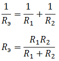
In the case of three resistors connected in parallel:


Mixed compound– a connection, which is a collection of serial and parallel connections. To find the equivalent resistance, you need to “collapse” the circuit by alternately transforming parallel and serial sections of the circuit.

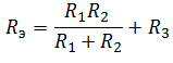
First, let's find the equivalent resistance for the parallel section of the circuit, and then add to it the remaining resistance R 3 . It should be understood that after the conversion, the equivalent resistance R 1 R 2 and resistor R 3 are connected in series.
So, what remains is the most interesting and most complex connection of conductors.
The bridge connection diagram is shown in the figure below.
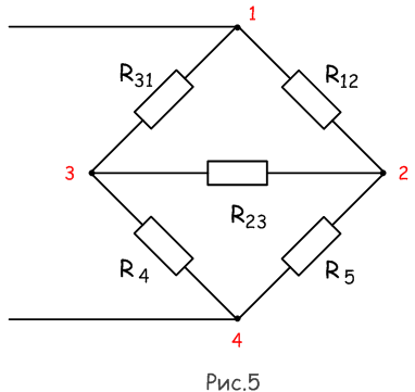
In order to collapse the bridge circuit, one of the bridge triangles is replaced with an equivalent star.

And find the resistances R 1, R 2 and R 3.
In the previous summary, it was established that the current strength in a conductor depends on the voltage at its ends. If you change conductors in an experiment, leaving the voltage on them unchanged, then you can show that at a constant voltage at the ends of the conductor, the current strength is inversely proportional to its resistance. Combining the dependence of current on voltage and its dependence on conductor resistance, we can write: I = U/R . This law, established experimentally, is called Ohm's law(for a section of chain).
Ohm's law for a circuit section: The current strength in a conductor is directly proportional to the voltage applied to its ends and inversely proportional to the resistance of the conductor.
First of all, the law is always true for solid and liquid metal conductors. And also for some other substances (usually solid or liquid). Consumers of electrical energy (light bulbs, resistors, etc.) can be connected to each other in different ways in an electrical circuit.D va main types of conductor connections

Series connection of conductors
When connecting conductors in series, the end of one conductor will connect to the beginning of another conductor, and its end to the beginning of a third, etc. For example, connecting light bulbs in a Christmas tree garland. When the conductors are connected in series, current passes through all the bulbs. In this case, the same charge passes through the cross section of each conductor per unit time. That is, the charge does not accumulate in any part of the conductor. Therefore, when connecting conductors in seriesThe current strength in any part of the circuit is the same: I 1 = I 2 = .
I: The total resistance of series-connected conductors is equal to the sum of their resistances R 1 + R 2 = R . Because when connecting conductors in series, they total length
increases. It is greater than the length of each individual conductor, and the resistance of the conductors increases accordingly. According to Ohm's law, the voltage on each conductor is equal to: U 1 = I* ,R 1 U 2 = I*R 2 . In this case, the total voltage is U = I( R1+ R 2) . Since the current strength in all conductors is the same, and the total resistance is equal to the sum of the resistances of the conductors, then: the total voltage on series-connected conductors is equal to the sum of the voltages on each conductor .
From the above equalities it follows that a series connection of conductors is used if the voltage for which the electrical energy consumers are designed is less than the total voltage in the circuit.
1) the current strength in all conductors is the same; 2) the voltage across the entire connection is equal to the sum of the voltages on the individual conductors; 3) the resistance of the entire connection is equal to the sum of the resistances of the individual conductors.
Example parallel connection conductors serve to connect electrical energy consumers in the apartment. Thus, light bulbs, a kettle, an iron, etc. are switched on in parallel.
When connecting conductors in parallel, all conductors at one end are connected to one point in the circuit. And the second end to another point in the chain. A voltmeter connected to these points will show the voltage on both conductor 1 and conductor 2. In this case, the voltage at the ends of all parallel-connected conductors is the same: U 1 = U 2 = U .
When conductors are connected in parallel, the electrical circuit branches out. Therefore, part of the total charge passes through one conductor, and part through the other. Therefore, when connecting conductors in parallel, the current strength in the unbranched part of the circuit is equal to the sum of the current strength in the individual conductors: I = I 1 + I 2 .
According to Ohm's law I = U/R, I 1 = U 1 /R 1, I 2 = U 2 /R 2 . This implies: U/R = U 1 /R 1 + U 2 /R 2, U = U 1 = U 2, 1/R = 1/R 1 + 1/R 2 The reciprocal of the total resistance of parallel-connected conductors is equal to the sum of the reciprocals of the resistance of each conductor.
When conductors are connected in parallel, their total resistance is less than the resistance of each conductor. Indeed, if two conductors having the same resistance are connected in parallel G, then their total resistance is equal to: R = g/2. This is explained by the fact that when connecting conductors in parallel, their cross-sectional area increases. As a result, resistance decreases.
From the above formulas it is clear why consumers of electrical energy are connected in parallel. They are all designed for a certain identical voltage, which in apartments is 220 V. Knowing the resistance of each consumer, you can calculate the current strength in each of them. And also the correspondence of the total current strength to the maximum permissible current strength.

1) the voltage on all conductors is the same; 2) the current strength at the junction of the conductors is equal to the sum of the currents in the individual conductors; 3) the reciprocal value of the resistance of the entire connection is equal to the sum of the reciprocal values of the resistance of individual conductors.
Need to calculate the resistance of series, parallel or combined circuits? Necessary if you don't want to burn the board! This article will tell you how to do it. Before reading, please understand that resistors have no "beginning" and no "end". These words are introduced to facilitate understanding of the material presented.
Parallel and series connection of conductors are methods of switching an electrical circuit. Electrical circuits of any complexity can be represented using these abstractions.
There are two ways to connect conductors; it becomes possible to simplify the calculation of a circuit of arbitrary complexity:
In practice, a mixed connection of conductors is more common, some are connected in series, some in parallel. You need to break the chain into simple segments and solve the problem for each separately. An arbitrarily complex electrical circuit can be described by a parallel, series connection of conductors. This is how it is done in practice.
Theory serves as the basis for the formation of solid knowledge; few people know how voltage (potential difference) differs from voltage drop. In physics terms, the internal circuit is the current source; the one located outside is called the external circuit. The demarcation helps to correctly describe the distribution of the field. The current does work. In the simplest case, heat generation follows the Joule-Lenz law. Charged particles, moving towards a lower potential, collide with crystal lattice, give off energy. The resistances heat up.
To ensure movement, it is necessary to maintain a potential difference at the ends of the conductor. This is called circuit section voltage. If you simply place the conductor in the field along power lines, the current will flow, it will be very short-lived. The process will end with the onset of equilibrium. External field will be balanced by its own field of charges, in the opposite direction. The current will stop. For the process to become continuous, an external force is needed.
The current source acts as such a drive for the movement of the electrical circuit. To maintain potential, work is done inside. Chemical reaction, as in a galvanic cell, mechanical forces- hydroelectric generator. The charges inside the source move in the direction opposite to the field. The work of outside forces is being done on this. You can paraphrase the above formulations and say:
The generator (current source) is equipped with two poles. The one with less potential is called negative, the other is called positive. In the case of alternating current, the poles continually change places. The direction of movement of charges is not constant. Current flows from the positive pole to the negative pole. The movement of positive charges goes in the direction of decreasing potential. According to this fact, the concept of potential drop is introduced:
The potential drop of a section of a circuit is the decrease in potential within the section. Formally, this is tension. For branches of a parallel circuit it is the same.
Voltage drop also means something else. The value characterizing heat losses is numerically equal to the product of the current and the active resistance of the section. Ohm's and Kirchhoff's laws, discussed below, are formulated for this case. In electric motors and transformers, the potential difference can differ significantly from the voltage drop. The latter characterizes losses on active resistance, while the first takes into account full time job current source.
When solving physical problems, for simplification, the motor can include an EMF, the direction of action of which is opposite to the effect of the power source. The fact of energy loss through the reactive part of the impedance is taken into account. School and university physics courses are distinguished by their isolation from reality. That is why students listen with open mouths about the phenomena taking place in electrical engineering. In the period preceding the era of the industrial revolution, the main laws were discovered; a scientist must combine the role of a theorist and a talented experimenter. The prefaces to Kirchhoff's works openly speak about this (Georg Ohm's works have not been translated into Russian). The teachers literally attracted people with additional lectures, flavored with visual, amazing experiments.

Ohm's and Kirchhoff's laws are used to solve real problems. The first one deduced equality purely empirically - experimentally - the second one began mathematical analysis problems, then tested my guesses with practice. Here is some information to help solve the problem:

The algorithm for calculating real circuits is simple. Here are some points regarding the topic under consideration:
The theses can easily be extended to arbitrary cases. The voltage drop across two open silicon diodes is equal to the sum. In practice it is 1 volt, exact value depends on the type of semiconductor element and characteristics. The same way Consider power supplies: when connected in series, the ratings add up. Parallel is often found in substations where transformers are placed side by side. The voltage will be the same (controlled by equipment), divided between the branches. The transformation coefficient is strictly equal, blocking the occurrence of negative effects.
Some people find it difficult: two batteries of different ratings are connected in parallel. The case is described by Kirchhoff's second law; physics cannot imagine any complexity. If the ratings of two sources are unequal, the arithmetic mean is taken, if the internal resistance of both is neglected. Otherwise, the Kirchhoff equations are solved for all contours. The unknown currents will be (three in total), the total number of which is equal to the number of equations. For complete understanding, a drawing has been provided.

An example of solving Kirchhoff's equations
Let's look at the image: according to the conditions of the problem, source E1 is stronger than E2. We take the direction of the currents in the circuit from common sense. But if they had entered it incorrectly, after solving the problem one would have turned out with negative sign. Then it was necessary to change direction. Obviously, current flows in the external circuit as shown in the figure. We compose the Kirchhoff equations for three circuits, this is what follows:
Connecting batteries of different ratings in parallel is definitely harmful. What is observed at a substation when using transformers with different transmission ratios. Equalizing currents do no useful work. Different batteries connected in parallel will begin to function effectively when the strong one drops to the level of the weak one.
Resistors are widely used in electrical engineering and electronics. They are mainly used for regulation of current and voltage circuits. Main parameters: electrical resistance (R) measured in Ohms, power (W), stability and accuracy of their parameters during operation. You can remember many more of its parameters - after all, this is an ordinary industrial product.
 A series connection is a connection in which each subsequent resistor is connected to the previous one, forming an unbroken circuit without branches. The current I=I1=I2 in such a circuit will be the same at each point. On the contrary, the voltage U1, U2 at its different points will be different, and the work of charge transfer through the entire circuit consists of the work of charge transfer in each of the resistors, U=U1+U2. According to Ohm's law, voltage U is equal to current times resistance, and the previous expression can be written as follows:
where R is the total resistance of the circuit. That is, simply put, there is a voltage drop at the connection points of the resistors and the more connected elements, the greater the voltage drop occurs
It follows that  , general meaning such a connection is determined by summing the resistances in series. Our reasoning is valid for any number of chain sections connected in series.
 Let's combine the beginnings of several resistors (point A). At another point (B) we will connect all their ends. As a result, we get a section of the circuit, which is called a parallel connection and consists of a certain number of branches parallel to each other (in our case, resistors). Wherein electricity between points A and B will be distributed along each of these branches.
The voltages on all resistors will be the same: U=U1=U2=U3, their ends are points A and B.
The charges passing through each resistor per unit time add up to forming a charge passing through the entire block. Therefore, the total current through the circuit shown in the figure is I=I1+I2+I3.
Now, using Ohm's law, the last equality is transformed to this form:
U/R=U/R1+U/R2+U/R3.
It follows that for the equivalent resistance R the following is true:
1/R=1/R1+1/R2+1/R3
or after transforming the formula we can get another entry like this:  .
.
How large quantity resistors (or other links in an electrical circuit that have some resistance) are connected in a parallel circuit, the more paths for current flow are formed, and the lower the overall resistance of the circuit.
It should be noted that the reciprocal of resistance is called conductivity. We can say that when sections of a circuit are connected in parallel, the conductivities of these sections are added up, and when connected in series, their resistances are added up.
It is clear that with a series connection, a break in the circuit in one place leads to the fact that the current stops flowing throughout the entire circuit. For example, a Christmas tree garland stops shining if just one light bulb burns out, this is bad.
But the series connection of light bulbs in a garland makes it possible to use a large number of small light bulbs, each of which is designed for mains voltage (220 V), divided by the number of light bulbs.
 Series connection of resistors using the example of 3 light bulbs and EMF
 But with a serial connection safety device its operation (rupture of the fuse link) allows you to de-energize the entire electrical circuit, located after it and provide the required level of security, and that’s good. The switch in the power supply network of the electrical appliance is also connected in series.
Parallel connection is also widely used. For example, a chandelier - all the bulbs are connected in parallel and are under the same voltage. If one lamp burns out, it’s not a big deal, the rest won’t go out, they remain under the same voltage.
 Parallel connection of resistors using the example of 3 light bulbs and a generator
 If it is necessary to increase the dissipation ability of the circuit thermal power released when current flows, both series and parallel combinations of resistors are widely used. For both serial and parallel methods of connecting a certain number of resistors of the same value general power is equal to the product of the number of resistors and the power of one resistor.
 Mixed connection of resistors
 A mixed compound is also often used. If, for example, it is necessary to obtain a resistance of a certain value, but it is not available, you can use one of the methods described above or use a mixed connection.
From here, we can derive a formula that will give us the required value:
Rtot.=(R1*R2/R1+R2)+R3
In our era of development of electronics and various technical devices at the heart of all difficulties lie simple laws, which are discussed superficially on this site and I think that they will help you successfully apply them in your life. If, for example, we take a Christmas tree garland, then the light bulbs are connected one after another, i.e. Roughly speaking, this is a separate resistance.
Not long ago, garlands began to be connected in a mixed way. In general, in total, all these examples with resistors are taken conditionally, i.e. any resistance element can be a current passing through the element with a voltage drop and heat generation.
Today we will look at the simplest and most ancient method of home preparation...

Salmon shish kebab is a wonderful dish that will be appreciated as...

Neptune salad may be unimpressive in appearance, but it has a rich and vibrant taste...