Creating your own decor is the best option for those who...


To your room. At first I wanted to make the main channel (for bass) on a microcircuit TDA2050 and for two satellites - on TDA2030. As you know, almost all inexpensive Chinese woofers are made this way. But then, after thinking a little, I decided not to be like my Chinese brothers and made it noticeably more powerful. I bought a microcircuit for the bass TDA7294, and for satellites I installed the already mentioned TDA2050. I think it will be good. Two speakers of 24 watts each and a main power of 60 watts.
Manufacturing started from the body
. This is the dustiest part of the job. I did not delve into the theory of all sorts of calculations of the Thiel-Smol parameters for the speaker and programs for calculating the volume of the box. I just estimated the approximate dimensions by eye and cut out blanks from chipboards with a jigsaw. Connected with self-tapping screws. I coated all joints with PVA glue. The box should be almost airtight. If large gaps remain, then you can’t even dream of any bass. I adjusted only the length of the bass reflex pipe for the best sound.
![]()


Now the tests: for a small room the bass is simply brutal! At medium volume levels, cabinet doors begin to creak. Well, neighbors, hang in there! I'll show you Kuzka's mother!

I bought two speakers as satellites 25AC-225 in a good condition. I didn’t want to bother with the satellite bodies either. In general, all that remains is to putty the body a little, sand it and cover it with self-adhesive or something else. I haven't decided yet. For now, I’ll listen a little and enjoy the quality of the new sound. The result was a good device for little money and made with your own hands. Now it will delight my ears, and also make life more fun for my neighbors :) All files are in the archive. Subwoofer manufactured and tested Boozer .
Discuss the article SUBWOOFER WITH YOUR OWN HANDS
I decided to write this article specifically for those who want, but for one reason or another cannot afford to purchase a subwoofer.
I will try to tell you in an accessible language for inexperienced people, and if possible, show you - how to make a subwoofer yourself, with your own hands.
Many people have the word on the tip of their tongue Subwoofer, but not everyone understands what it is.
SUBWOOFER comes from two words SUB and WOOFER - literally translated - subwoofer, i.e. speaker system for reproducing sound at lower frequencies (from approximately 20 to 100 Hz). Many people call it a “bass speaker”. Subwoofers can be active or passive. Active means that the speaker body houses an amplifier and power supply, Passive means it needs an external amplifier.
The following abbreviations are also used in the text:
AC- an acoustic system, or, simply put, a “speaker”.
Speaker- it’s also a loudspeaker, but “dynamic head” would be more correct.
LFO- low frequency signal generator. (low frequencies mean frequencies from 20 to 20000 Hz)
ULF- amplifier of low-frequency signals.
Step one.
Tool and material.
To make a subwoofer we need to find:
1. Self-confidence, the desire to relentlessly go to the end and be ready for material costs (maybe it will work out well!).
2. A good, proven tool, namely:
- wood hacksaw;
- chisel;
- a set of files of various calibers and types: flat, triangular, round;
- skins (from small to large);
- electric drill;
- a screwdriver (you can also use a screwdriver);
- jigsaw (even better - jigsaw);
- ruler, pen, pencil, sheet of paper and other office supplies;
- a compass (preferably with a wingspan of 20-25 cm);
- PVA wood glue or other wood glue;
- building materials for the body, namely: plywood with a thickness of 10mm to 20mm, or chipboard, or MDF.
- wooden blocks 20x20, 30x30, 40x40, etc.
- a mountain of self-tapping screws from 10mm to 50mm, we will need a lot of them!
3. a computer on which it is very desirable to install the JBLSpeakerShop program or any other program for calculating the box.
Step two.
Loudspeaker (speaker) parameters.
Each of us has a first name, last name, and patronymic. Each of us has unique facial features, eye color, fingerprints, and retinal patterns. There are no identical people in the world. In the same way, no two speakers are the same; each of them has its own unique parameters. Even if you take two identical speakers made at the same factory on the same day, their parameters will differ, of course slightly, but this small difference can be important. What I mean is that before we start making a subwoofer, we MUST calculate the main parameters of our speaker. Whether you bought it in a store, unscrewed it from an old speaker, or a friend brought it from the garage, in any case you need to measure its characteristics. In the future, based on these parameters, we will choose the type of box for the subwoofer.
We will write down the parameters necessary to calculate the subwoofer on a piece of paper and save it until the moment when the sound quality of the manufactured “boom box” is completely satisfactory.
So, let's begin. Since most of the currently existing programs for calculating AC boxes use the Till-Small parameters, it is these that we will calculate.
In order to start calculating the box, we need the following parameters:
Phnom- The rated power of the speaker is given in the brand of the head (75GDN-1 75W).
Fs- Frequency of the speaker’s own resonance in open space.
Fc- Resonant frequency in a closed box.
Qts- Full quality factor at resonant frequency.
Qes- Electrical quality factor at resonant frequency.
Qms- Mechanical quality factor at resonant frequency.
Vas- Equivalent speaker volume.
D- Effective diffuser diameter.
Xmax- Maximum diffuser displacement.
In principle, other parameters may be needed, but these are already enough to start calculations. To measure the parameters you will need a calculator, a voltmeter (preferably a digital multimeter), a low-frequency generator, a hermetically sealed box of 20 liters, and you will also have to make a simple device.
Low frequency generator - you can take any one, for example G3-109 or similar. If there is no generator, then you can use a computer. We connect an amplifier to the linear output of the sound card, and from the output of the amplifier, through a 1KOM resistor, we connect the speaker under test. The resistor power should be 2W or more, otherwise it will get very hot. In principle, everything is ready. If we use a computer instead of a generator, then we need to download a program - LFO, there are a huge number of them on the network.
So, let's begin.
We hang the speaker on a rope in the center of the room to the ceiling, perhaps by a chandelier or in some other way, the main thing is that there are no objects nearby, this can affect the accuracy of the measurement.
Everything is connected, we launch the LFO program, set the frequency to 1000Hz. On the computer, set the volume to the middle position to eliminate distortion of the signal shape. connect the multimeter to the output of the amplifier. By adjusting the volume on the amplifier we set the voltage to 20V.
Attention! Now it is absolutely impossible to adjust the volume either on the amplifier, or on the computer or LFO.
We connect the voltmeter directly to the speaker. We set the generator frequency to approximately 5-10 Hz and gradually increase the frequency and monitor the voltmeter readings. We need to find the resonant frequency of the speaker, at this frequency the voltmeter will show the maximum voltage, then it will begin to decrease. So the voltmeter showed the maximum value - we write it down on our sheet as Umax. Then we record the frequency of the generator at which the maximum voltage value is recorded, this will be Fs - the resonant frequency. Now we need to find the minimum amplitude value. We again begin to gradually increase the frequency relative to Fs until the voltmeter readings stop changing, write this value as Umin, with a further increase in frequency the amplitude will increase again, but this is no longer important to us.
 Now we know several parameters of our head, but this is just the beginning. Using a generator and a voltmeter, we can plot the frequency response graph shown on the left. It shows Umax - corresponding to the voltage at resonance, as well as Fs - the resonant frequency - the peak on the graph. We also found Umin, but what is Usr, you say, and what are these F1 and F2?
These are the frequencies with which we will determine the quality factor of the speaker. Previously, I calculated these parameters manually, calculated them using the formulas Uav, Qts, Qes, Qms. Now there is a useful program TSCalc, you need to download it right now - download. Working with it is simply simple; we substitute the values and get the result. First you need to find out Rmax, to do this we multiply Umax by 1000 and write the value on a piece of paper. You will also need to measure the speaker's DC resistance using an ohmmeter, write it as Re.
Now let’s substitute the values of Rmax and Re into the program and find Rx. Divide Rx by 1000 and get Uav. Now let's find F1 and F2. We begin to reduce the frequency relative to Fs “down” and when the voltmeter shows the voltage Uav we write down F1, now the same thing only “up” from Fs and write down the value of F2. Now we substitute the values of Fs, F1, F2 into the program. And we get the values Qes, Qms, Qts.
It's time for the pre-prepared box. We take our speaker and screw it to the box with the magnet facing outwards, there is no fundamental difference in this, it’s just more convenient. Now we find the resonant frequency again, but write it as Fc. We substitute the value of Fs, Fc and the known volume of the box, we get the value Vas - the equivalent volume.
Well, that's basically all. The effective diameter of the diffuser and its maximum displacement are measured using an ordinary ruler. Don't forget to write down the values on the sheet.
If you have difficulties with measurement, or you don’t get a clear result, you can use the characteristics included on the “sheet” along with the speaker, or the official factory characteristics.
Step three.
Types of boxes.
Now we have a speaker, we have its real parameters, we can start choosing a box.
I want to disappoint you right away. It is based on the parameters of the speaker that the type of housing is selected. I’m not saying that you won’t be able to assemble the box you want with it, it just may not sound the same as it would in the “native” box.
So, types of boxes, or options for subwoofers.
 |
Free emitter or Free air This option may be suitable for speakers with Fs above 100Hz. |
 |
Closed Box or Closed Box. Select this box if Qts product Fs/Qts=50 |
 |
Bass reflex or Vented Box. Choose if Qts product Fs/Qts=85 |
 |
Passive Radiator. A passive radiator is like a bass reflex, only instead of a pipe there is an emitter-membrane. |
 |
Band Pass or Band Pass Band Pass can be literally translated as Band Pass. |
 |
Band Pass 6th order A Band Pass 6th order class A. |
 |
Band Pass 6th order B Band Pass 6th order class B. |
Any of these housing options can be assembled with either one or two speakers.
You know the parameters of your speaker, what will come out of it, you have already determined it, it’s time to calculate the box.
Step four.
Box calculation.
Unpack the downloaded JBLSpeakerShop program into the root folder of the disk. Then run the setup.exe file from the DISK1 folder. The installation will begin, enter the path of the second part of the DISK2 archive. Installation completed.
Launch the program Start => Programs => JBL SpeakerShop => SpeakerShop Enclosure Module.
I won’t tell you in detail about the program, it is very simple and in principle everything is clear.
First, go to the menu Loudspeaker- and enter the parameters of our head. Then, having selected the box type, click - Box - Parameters- and there already on the selected type. All that remains is to enter the volume and frequency of the desired resonance; you need to experiment with these parameters, observing the resulting graphs. After selecting the mailbox parameters, click Vent, here we enter the parameters of the pipe (bass reflex) if it exists, of course. It remains to calculate the dimensions of the box, submenu Dimensions, choose the shape and size to suit your taste. On the menu Graphs- selection of types of displayed graphs.
To the fullest, print out the graphs, parameters, sizes - Ctrl+P.
Step five, final.
Making a box.
Now, having rested a little, let’s get down to making the box. At this stage, in order not to translate precious material, you must strictly follow the rule, “measure seven times, drink once.”
We take out the prepared tools, material, patience. When choosing plywood or chipboard (whoever has what), you need to take into account that the higher the power of the speaker, the higher the thickness of the box walls and the more rigid the fastening. The best material is, of course, plywood (you shouldn’t use old, dried-out plywood - it will simply crumble), much stronger than chipboard, I don’t even understand how you can make a good subwoofer from sawdust.
We took out a ruler and a pencil, and first of all, let’s draw all the sides of the box on a sheet of plywood. Try to save money, in case you make a mistake somewhere, you will have something to correct.
Now let's cut, a good tool would be a hacksaw with a guide and fine teeth. You need to cut slowly and preferably at an angle, you don’t want the plywood to delaminate and crack. You can also use a jigsaw, preferably with a speed controller, for the reasons already stated. Saw smoothly, don’t rush, you’ll have a hard time using a file to straighten the humps and depressions.
After cutting, you still have to work with a file, you need to remove all the protruding pieces of wood, otherwise splinters, iodine, bandages.
Take out wooden blocks, choose their sizes yourself, but of course not too small or huge. Place the walls together as they should be and measure the required length of the bars.
Another crucial point in making the box is the huge hole for the speaker. First, using a compass, we mark a circle for the speaker, slightly larger than the diameter of the diffuser along with the rubber surround. And another smaller circle, equal to the radius of the drill and adding another 2-3mm. Here are a few ways to make holes in a piece of plywood. Don’t look for a drill, there are hardly any drills with a diameter of 100-300mm in the world, and you’ll need a giant drill. Take a drill with a diameter of 10-15mm, a regular electric drill. Drill by laying your piece of plywood on some other scrap piece of wood, this will save the bottom surface a little from cracking. Now we drill holes along the inner circumference at a distance of 1-2 mm from each other. When finished, take a narrow chisel and a hammer and punch the bridges between the holes, then knock out the resulting pancake. We take the largest round file, or better yet a rasp, and slowly, again at a slight angle, align the circle along the drawn line. Sharp corners on the front side can be rounded. In the same way we make holes for the bass reflex. Another way: draw a circle with the radius of the diffuser and a hole inside, and then use a jigsaw to cut along the line. Faster, but more chips! Attach the speaker to the hole, if the “hole” suits you, drill holes for fastening the head, and for fastening you can use screw-in metal double-sided nuts, they are used in the furniture industry.
Don't forget the plug! It is better to use concert acoustics - more reliable and practical.
Well, we’ve made all the walls, holes for the speaker and bass reflex, cut the bars, and we’ll assemble them.
Using the drill again, we place a drill half the diameter of the screws and drill through the sheets of plywood in the places where it will be attached to other sheets and bars. Now take PVA glue or wood glue and spread it thicker at the joints. We connect the walls together and screw self-tapping screws into the holes made; it’s okay if they go right through and are not visible inside, but strength is important to us. The glue will play two roles, increasing the strength of the fastener and sealing it. Make sure that the structure is not warped, that the corners are even, there must be beauty and neatness.
Do not screw the back wall yet, it will still serve us. Attach the speaker, from the outside or from the inside, as you like and depending on the design of the speaker. Coat the junction of the plywood with the speaker with autosealant, being careful not to get it on the diffuser. Auto sealant - will ensure tightness and can be easily removed if you suddenly want to change the head for another one or during repairs.
Bass reflex - you can use a piece of plumbing pipe, an aluminum pipe, or basically any pipe you have (except for metal water and sewer pipes). In the program, enter its dimensions and get the length. The bass reflex can be square, then you will need to show your imagination in its manufacture. It will also need to be secured, but not tightly yet.
How to make a damper. The damper material can be: felt, hard foam rubber, cotton wool, thick fleece, etc. The most affordable material is cotton wool. But you can’t just stuff it inside! Here our beloved women will come to our aid, who all the time of our efforts grumble about garbage, noise and a bunch of tools mixed with pieces of wood, etc. How will they help us? Yes, it’s very simple, women’s tights, you can stuff cotton wool into them and make sound-absorbing “sausages”, which we will glue to the walls of the box.
Setting up the bass reflex. After damping, we put the back cover in place, but so that it can be removed later. Although if your speaker is pulled out, then the back wall can be firmly fixed with glue and a bunch of screws. We connect the unit to the low-frequency generator through an amplifier, and a voltmeter to the contacts of the subwoofer (i.e., the speaker located inside). By changing the frequency of the generator, we find the resonant frequency Fc using an already known method. If the resonant frequency differs from the calculated one, we will adjust it using a bass reflex and the amount of damper inside the box. The bass reflex pipe will need to be either shortened or lengthened; in some cases, the pipe may be longer than the dimensions of the subwoofer, in which case it will be necessary to change its diameter. You also need to experiment with the amount of damper, remove or add, decide on the specific situation. When the resonant frequency suits you, you can firmly fix the bass reflex or damper.
Turn on the music, the louder the better, listen for any extraneous noise, whistling, or rustling. If it whistles, it means there is a hole or gap left unclosed somewhere in the drawer, cover it with putty or sealant, and fill it with glue. If it rustles, the damper may be touching the moving speaker cone.
Now the final external processing of the box, the corners can be rounded, thoroughly sanded, and the cracks and holes can be covered with mastic or putty.
In the end, you can cover the subwoofer with vorsonite or some other material, put decorative grilles on the speaker and bass inertizer, screw on the legs if you are going to use it indoors, your imagination will tell you here.
Well, that seems to be all! I hope all my writing has helped someone! Thank you for reading to the end, all the best to you, success!
Pavel Parygin
Kyiv
I probably won’t reveal much of a secret if I say that the small-sized speakers that are equipped in car audio systems do not provide good “bass” reproduction. One of the possible ways to solve this problem is also well known - to supplement the stereo system with an active subwoofer (an amplifier common to the right and left stereo channels with its own speaker, which reproduces low-frequency components of the sound range up to 200-250 Hz). But such an acoustic unit with an additional amplifier costs almost more than the entire stereo system taken together. That's why I decided to take on making it myself.
In order to make an active subwoofer in a car with my own hands, I purchased a 10-inch ALTRONIX E-RSW1039A low-frequency speaker (Fig. 1), two electronic kits for radio amateurs - an active signal processing unit for the subwoofer channel and a powerful single-channel low-frequency amplifier NM2034 ( in the form of a finished unit BM2034), 5 m of a special cable (ROCAR HIENDPCOFC SPEAKER CABLE) for connecting the speaker system, housing for assembling electronics (Z-4A), terminals, connectors, plugs.
Fig.1. ALTRONIX E-RSW1039A woofer
But first we had to start manufacturing a “closed box” type speaker system housing with a bass reflex (Fig. 2).

Fig.2. The design of the subwoofer housing is closed type with a bass reflex.
The useful volume of the body V, diameter d, length L of the bass reflex and other parameters were calculated on a computer using the JBL SpeakerShop program. The program performs all these calculations based on the characteristics of the speaker used (total quality factor Qts, resonant frequency Fs, equivalent volume Vas, etc.). In my case it turned out: d=60 mm, l=96 mm. For speakers of another type, these parameters will naturally be different, and appropriate changes must be made to the design of the acoustic unit.
The easiest way to make a housing for a car subwoofer at home is in the form of a round barrel, with a speaker built into one of the bottoms. In this case, both bottoms can be cut with a jigsaw from chipboard or multi-layer plywood (Fig. 3), and the cylindrical body is bent from a sheet of fiberboard.

Fig.3. Both round bottoms of the body were cut out of chipboard with a jigsaw.
At first I doubted the strength of such a design and assumed to glue two layers, but after completing the assembly, all my doubts were dispelled, since the body turned out to be very rigid and with fiberboard in one layer. It turned out to be quite simple to bend a blank from a sheet of fiberboard into a cylinder. To do this, it is enough to steam it from the outside, ironing it through a wet hoe.
After the fiberboard sheet was bent, I glued the round bottoms with PVA and additionally secured them with staples using a construction stapler. The finished body was covered with carpet on the outside (glued and secured with staples) (Fig. 4).

Fig.4. The finished building is covered with carpet.
Finally, I glued in the bass reflex, attached an insert with terminals for connection to the rear panel, soldered the wires and installed the speaker in place. Everything turned out very well (Fig. 5).

Fig.5. Active subwoofer assembled.
There were no problems with assembling the electronics. Both sets include fairly detailed and understandable instructions, according to which everything can be assembled and connected easily and simply (Fig. 6).
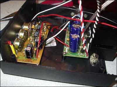
Fig.6. There were no problems with assembling electronics from MASTER KIT kits.
The only thing I did not follow the instructions was that instead of the 600 cm2 radiator recommended for the power amplifier chip, I installed a central processor radiator (Socket 370 connector) with a fan left over from upgrading the computer. The replacement turned out to be quite acceptable.
And finally, I specially moved the electronics into a separate housing, although it would be more rational to place it in the housing of the acoustic unit, separating a special compartment for this. But I really wanted to turn all these knobs myself and adjust the subwoofer directly inside the car while listening to real music. Therefore, I placed the assembled amplifier in the glove box (Fig. 7), and additionally installed a separate power switch on its front panel.
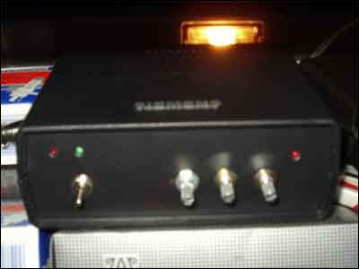
Fig.7. The electronic unit of the subwoofer is installed in the glove box, colloquially called the “glove box”.
A stereo system with a homemade car subwoofer sounds no worse than with a branded one, and costs several times less. But the main thing is that I made the subwoofer with my own hands!
Due to the fact that the BM2034 amplifier is no longer in production, Master Kit recommends using
How to make a subwoofer in a car with your own hands? The matter is quite simple. if you understand its purpose and components. A subwoofer is an acoustic system that reproduces low frequencies in the sound range of 20-120Hz. It is necessary to create full surround sound, especially relevant for dance and rock music. The average acoustic system is not capable of reproducing this range, since it is not fully recognized by the human ear.
We hear bass, feel vibrations, in general - this is just right for a car, you can install it anywhere. However, we recommend using the luggage space, there will be plenty of space there and will not interfere with anyone. The dimensions of the future subwoofer are determined by the speakers you selected. As a rule, they have a fairly large diameter.
Making a homemade subwoofer for a car is not difficult: assemble a box and install a speaker in it, the main thing in this matter is to choose a speaker. We advise you to listen to this information. It will help you achieve sound quality and your efforts will not be in vain.
Making a subwoofer with your own hands includes the following steps:
Decide on the sizes. The following models are currently available on the market:
Important! Decide on the resistance, a load of 1-2 ohms will significantly spoil the sound, the optimal resistance for a subwoofer speaker is 2-4 ohms.
There has traditionally been a long-standing debate about the power of the speakers; it is difficult to state anything definitely. There is only one rule: the power of the speaker must exceed the power of the amplifier. Why? It's simple: no speaker will last long operating at maximum power, so it needs a “margin of safety” in the form of such a difference. If you already have both a speaker and an amplifier, we advise you to determine this difference and make a mark on the amplifier controls with the maximum allowable volume for the subwoofer. Not a single speaker will maintain sound quality at maximum volume; over time (sometimes immediately), the imbalance will terribly hurt the ear.
Now you don’t need to carry out complex calculations yourself; we recommend using the WinISD 0.44 program. It will create a virtual image of a subwoofer for a car, based on the following dynamics data (can be found on the label), called Thiel-Small parameters:

After entering the parameters, select the option ZY - closed box and you can independently adjust the frequencies of the phase inverters or use the standard parameters.
Based on all the entered parameters, you will receive a sketch of the box; if you stick to the design when making a subwoofer with your own hands, you will get the most optimal and possibly acceptable sound for your speaker.
Important! Select materials that meet your objectives: sound insulation, density and strength.
Practice shows that the ideal material is MDF (medium-density particle board); in extreme cases, high-quality plywood will also do. Chipboard is also used, but in all three characteristics it loses significantly. How to make a subwoofer at home without spending money? Use available materials. In principle, with proper arrangement, the doors of old Soviet furniture, probably left in everyone’s closet, will also work.
A subwoofer for a car must be covered (except for the front panel - it is a matter of taste) with soundproofing material; ordinary office-type carpet works well.

Remember - plastic looks nice on subwoofers, but it will be a serious detriment to sound quality. You need to decide whether the subwoofer will become a fashionable interior component or a quality addition to the speaker system.
So, we have prepared a virtual model, decided on the material and place in the car.
Box assembly:

In order to independently install and connect a ready-made subwoofer to a car, you will need the following consumables: wiring, including tulips and wires for connecting to the amplifier, fuses, insulating tape and one capacitor.
Carefully install the finished subwoofer in the place prepared in advance. You can use a tie to secure it. That's all, all that remains is to connect it.
The subwoofer is connected to the amplifier, and it is connected to the car radio. It is the amplifier that distributes the radio signals to the high-frequency speakers and subwoofer. Be prepared to run the wires, hiding them under the seats, through the entire cabin from the trunk, where the amplifier and subwoofer are installed (usually), connecting the wires to the radio and battery.
It happens that the amplifier is simply missing from the car. and even a well-assembled subwoofer with your own hands will not give the desired effect without it. We offer an alternative to purchasing - a homemade subwoofer amplifier.
This is a circuit for assembling an amplifier for a car.
Required components:
Also prepare the amplifier housing, operating switch, wires, tulip connectors and radiator.

Advice! After the board is ready and the circuit is complete, do not rush to assemble the amplifier, connect the contacts to the speaker and check its operation, starting with the minimum volume.
In order to do everything correctly and quickly, we recommend watching a video lesson on how to make a subwoofer for a car at home:
A subwoofer is a low-frequency speaker used to improve the sound of music. Reproduces sounds at frequencies from 5 to 200 hertz. That is, the bass is enhanced and music, especially rhythmic, sounds much better and louder. A sub can be installed in a car in a workshop, from specialists, but you can do it yourself.
First you need to decide on the speaker, based on the free space in the car.
The basic principle of the difference in resistance in a voice coil is: the lower the load resistance of the amplifier, the higher the power. It is recommended to select 2-4 Ohms.
Also, we can say for sure that the speaker should be chosen more powerful than the maximum power of the amplifier. But you shouldn’t take a speaker that’s too powerful either, as there won’t be enough power to “drive” it.
Designing a virtual image of a box is best done in the WinISD 0.44 program.
By design, subwoofers are divided into:

The subwoofer can be made of fiberglass or plywood. As a rule, it is installed in the luggage compartment. But it will be quite difficult for a beginner to cope with fiberglass. Therefore, we will consider in detail the manufacturing process from plywood. This is one of the simplest models of a closed-type subwoofer with a bass reflex, which you can make yourself.
What we need to make a subwoofer:

If you can’t find such plywood, then any thicker than 10 mm will do. But the greater its thickness, the less it will vibrate and, accordingly, the less additional subwoofer sound interference there will be.
And, finally, a bass reflex pipe, an amplifier are installed and the terminals are soldered in order to connect the wires.
Also, the subwoofer box can be trapezoidal in shape. And it’s even easier to make than the previous one.
The set of tools remains the same as for a cylindrical box.


The dacha is one of the most popular places for family holidays in the warm season....

Powerful low-voltage microwave transistors for mobile communications Magazine...