Alena Grishchuk Traditions and culture of the Christian family, in moral education...


Let's look at standard general purpose threads.
Metric thread is the main fastening thread. This is a single-start thread, mostly right-handed, with large or small pitch. The metric thread profile is an equilateral triangle. The protrusions and protrusions of the thread are blunted (Fig. 204) (GOST 9150-81).
Rice. 204 Metric thread
Cylindrical pipe thread has a profile in the form of an isosceles triangle with an apex angle of 55° (Fig. 205), the peaks and valleys are rounded. This thread is used in pipelines and pipe connections (GOST 6351-81).
Rice. 205 Cylindrical pipe thread
Trapezoidal thread serves to transmit movement and effort. The profile of a trapezoidal thread is an isosceles trapezoid with an angle between the sides of 30° (Fig. 206). For each diameter, the thread can be single-start or multi-start, right-handed or left-handed (GOST 9484-81).

Rice. 206 Trapezoidal thread
Thread persistent has a profile of an unequal trapezoid (Fig. 207). The profile depressions are rounded and there are three different pitches for each diameter. Serves to transmit movement with large axial loads (GOST. 10177-82).

Rice. 207 Thread persistent
Round thread for bases and sockets, for safety glasses and lamps, for sanitary fittings (GOST 13536-68) has a profile obtained by pairing two arcs of the same radius (Fig. 208) (GOST 13536-68).

Rice. 208 Round thread
Conical inch thread with a profile angle of 60° (GOST 6111-52) is used for hermetic connections in pipelines of machines and machines; cut on a conical surface with a taper of 1: 16 (Fig. 209).

Rice. 209 Tapered inch thread
Conical pipe thread has a profile similar to the profile of a cylindrical pipe thread; used in valves and gas cylinders. It is possible to connect pipes having a conical thread (taper 1: 16) with products having a cylindrical pipe thread (GOST 6211-81).
Special threads- these are threads with a standard profile, but different from the standard diameter or thread pitch, and threads with a non-standard profile.
Non-standard threads - square and rectangular(Fig. 210) - are manufactured according to individual drawings, on which all thread parameters are specified.

Rice. 210 Non-standard threads
Thread image in the drawing is carried out in accordance with GOST 2.311-68. On the rod, the threads are depicted with solid main lines along the outer diameter and solid thin lines along the inner diameter. In Fig. 211, and the thread on the cylinder is shown, and in Fig. 211, b - on a cone.

Rice. 211 Image of thread in the drawing
In the hole, the threads are depicted with solid main lines along the internal diameter and solid thin lines along the outer diameter. In Fig. 212, and the thread is shown in a cylindrical hole, and in Fig. 212, b - conical.

Rice. 212 Image of thread in hole
In the images obtained by projecting the threaded surface onto a plane perpendicular to its axis, a continuous thin line is drawn with an arc for 3/4 of the circumference, open anywhere, but not ending at the axes. When depicting a thread, a solid thin line is drawn at a distance of at least 0.8 mm from the main line and no more than the thread pitch. The visible thread boundary is drawn as a solid base line at the end of the full thread profile to the line of the outer diameter of the thread. The thread run-out is depicted as a solid thin line, as shown in Fig. 213.

Rice. 213 Thread run-out
Chamfers on a threaded rod or in a threaded hole that do not have a special structural purpose are not depicted in projection onto a plane perpendicular to the axis of the rod or hole. A solid thin line of the thread image should intersect the chamfer boundary line (Fig. 213, 214). Hatching in sections and sections is brought to a solid main line.

Rice. 214 The thread image line must intersect the chamfer boundary line
A thread with a non-standard profile is depicted as shown in Fig. 215, with all dimensions and additional data with the addition of the word "thread".

Rice. 215 Image of a thread with a non-standard profile
In threaded connections, the thread is conventionally drawn on the rod, and in the hole - only that part of the thread that is not covered by the rod (Fig. 216).

Rice. 216 Threaded connections
The thread designation includes: thread type, size, thread pitch and stroke, tolerance range, accuracy class, thread direction, standard number.
The type of thread is conventionally designated:
M- metric thread (GOST 9150-81);
G- cylindrical pipe thread (GOST 6357-81);
T g- trapezoidal thread (GOST 9484-81);
S- thrust thread (GOST 10177-82);
Rd- round thread (GOST 13536-68);
R- external conical pipe (GOST 6211-81);
Rr- internal conical (GOST 6211-81);
Rp- internal cylindrical (GOST 6211-81);
TO- conical inch thread (GOST 6111-52).
Size of Tapered Threads and Straight Pipe Threads conventionally indicated in inches (1" = 25.4 mm), for all other threads the outer diameter of the thread is indicated in millimeters.
Thread pitch is not indicated for metric threads with coarse pitch and for inch threads; in other cases it is indicated. For multi-start threads, the thread designation includes the thread lead, and the pitch is indicated in parentheses.
Thread direction indicate only for left-hand threads (LH).
The tolerance field and thread accuracy class may not be indicated on training drawings.
Profile thread is established by GOST 9150-81 and is a triangle with an apex angle of 60 degrees.
This is the main type of fastening thread. Designed for connecting parts directly to each other or using standard products with metric threads - bolts, screws, studs, nuts.
Its main elements and parameters are specified in millimeters (GOST 24705-81).
According to GOST 8724-81, metric threads are made with large and fine pitches on surfaces with a diameter of 1 to 68 mm; above 68 mm, the thread has only a fine pitch, and the fine pitch of the thread can be different for the same diameter, and the large one has only one meaning. The large pitch is not indicated in the thread symbol. So, for a thread with a diameter of 10 mm, the large thread pitch is 1.5 mm, fine- 1.25; 1; 0.75; 0.5 mm.
M18-6g metric external thread, nominal diameter 18 mm, coarse pitch, thread tolerance range 6g;
M18x0.5-6g the same, fine pitch R=0,5;
M18LH-6g the same, but left;
M18-6N metric internal thread, nominal diameter 18 mm, coarse pitch, thread tolerance range 6N.
Currently, there is no standard that regulates the main dimensions of inch threads. The previously existing OST NKTP 1260 has been canceled, and the use of inch threads in new designs is not allowed.
Triangular profile thread with an apex angle of 55°.
Thread pipe cylindrical
In accordance with GOST 6311-81, cylindrical pipe threads have an inch thread profile, i.e. isosceles triangle with an apex angle of 55°.
Threads are standardized for diameters from 1/16" to 6" in number of pitches z from 28 to 11. The nominal thread size is conventionally related to the internal diameter of the pipe (to the nominal diameter). Thus, a thread with a nominal diameter of 1 mm has a nominal diameter of 25 mm and an outer diameter of 33.249 mm.
Examples of symbols:
G1 1/2 -A cylindrical pipe thread, 1 1/2 nominal bore in inches, accuracy class A;
G1 1/2 LH-B-40 the same, but left, accuracy class B, make-up length 40 mm.
 Thread persistent |
Thread with a profile in the form of an equilateral trapezoid with an angle of 30°. Used to transmit reciprocating motion or rotation in heavily loaded moving threaded connections. Often used in the manufacture of lead screws, according to GOST 24738-81 it is performed on surfaces with a diameter of 8 to 640 mm.
Trapezoidal thread can be single-pass(GOST 24738-81, GOST 24737-81) and multi-pass(GOST 24739-81). GOST 9484-81 establishes a trapezoidal thread profile.
Tr40 X 6 -trapezoidal single-start thread with an outer diameter of 40 mm, pitch 6 mm.
R thread with a profile in the form of an unequal trapezoid with a working side angle of 3° and a non-working side-30 o. Thrust thread, like trapezoidal, May be single-pass And multi-pass. Performed on surfaces with a diameter from 10 to 640 mm (GOST 10177-82). It is used to transmit large forces acting in one direction: in jacks, presses, etc.
Example of a symbol:
S80x 10 -persistent single-start thread with an outer diameter of 80 mm, pitch 10 mm;
S80x 20(P10)-persistent multi-start thread with an outer diameter of 80 mm, a stroke of 20 mm, a pitch of 10 mm.
This p the thread has a rectangular (or square) non-standard profile, so all its dimensions are indicated in the drawing. It is used to transmit the movement of heavily loaded moving threaded connections. Typically performed on weight and lead screws.
Threads with a round profile (GOST 6242-83) have a relatively long service life and increased resistance under significant loads. It is used in the manufacture of frequently screwed connections (spindles, valves, etc.) operating in a polluted environment, as well as thin-walled parts with rolled or stamped threads (electric lamp base, etc.).
Example of a symbol:
Rd16-round thread with outer diameter 16 mm.
If round threads are used in connections of sanitary fittings, then its designation will be as follows: Kr12x2.54 (GOST 13536-68).
Metric thread
The thread profile is established by GOST 9150-81 and is a triangle with an apex angle of 60° (Figure 105).
This is the main type of fastening thread, intended for connecting parts directly to each other or using standard products with metric threads, such as bolts, screws, studs, nuts.
Figure 105 - Metric thread profile
Its main elements and parameters are specified in millimeters (GOST 24705-81).
According to GOST 8724-81, metric threads are made with large and fine pitches on surfaces with diameters from 1 to 68 mm - over 68 mm, the thread has only a fine pitch, and the fine pitch of the thread can be different for the same diameter, and the large one has only one meaning. The large pitch is not indicated in the thread symbol. For example: for a thread with a diameter of 10 mm, the large thread pitch is 1.5 mm, the fine one is 1.25; 1; 0.75; 0.5 mm.
M18-6g metric outer thread, nominal diameter 18 mm, pitch large, thread tolerance range 6g;
M18x0.5-6g metric outer thread, nominal diameter 18 mm, thread tolerance range 6g, fine pitch P=0.5;
M18LH-6g metric outer thread, nominal diameter 18 mm, large pitch, thread tolerance range 6g, left;
M18-6N metric internal thread, nominal diameter 18 mm, pitch large, thread tolerance range 6N.
Inch thread
Currently, there is no standard regulating the main dimensions of inch threads. The previously existing OST NKTP 1260 has been canceled, and the use of inch threads in new designs is not allowed.
Triangular profile thread with an apex angle of 55° (Figure 106).

Figure 106 - Inch thread profile
Pipe cylindrical thread
In accordance with GOST 6367-81, a cylindrical pipe thread has an inch thread profile, i.e. an isosceles triangle with an apex angle of 55° (Figure 107).
Threads are standardized for diameters from 1/16" to 6" in number of pitches z from 28 to 11. The nominal thread size is conventionally related to the internal diameter of the pipe (to the nominal diameter). Thus, a thread with a nominal diameter of 1 mm has a nominal diameter of 25 mm and an outer diameter of 33.249 mm.
Figure 107 - Parallel pipe thread profile
Examples of symbols:
G1 1/2 -A cylindrical pipe thread, 1 1/2 nominal bore in inches, accuracy class A;
G1 1/2 LH-B-40 cylindrical pipe thread, 1 1/2 nominal diameter in inches, left, accuracy class B, make-up length 40 mm.
Trapezoidal thread
Thread with a profile in the form of an equilateral trapezoid with an angle of 30° (Figure 108). Used to transmit reciprocating motion or rotation in heavily loaded moving threaded connections. Often used in the manufacture of lead screws, according to GOST 24738-81 it is performed on surfaces with diameters from 8 to 640 mm.
Trapezoidal thread can be single-pass(GOST 24738-81, GOST 24737-81) and multi-pass(GOST 24739-81). GOST 9484-81 establishes a trapezoidal thread profile.

Figure 108 - Trapezoidal thread profile
Example of a symbol:
Tr40x6- trapezoidal single-start thread with an outer diameter of 40 mm, pitch 6 mm.
Thread persistent
Thread with a profile in the form of an unequal trapezoid with an angle of the working side of 3° and the non-working side - 30° (Fig. 109). Thrust thread, like trapezoidal, May be single-pass And multi-pass. Performed on surfaces with diameters from 10 to 640 mm (GOST 10177-82). It is used to transmit large forces acting in one direction: in jacks, presses, etc.

Figure 109 - Thrust thread profile
Example of a symbol:
S80X10 - persistent single-start thread with an outer diameter of 80 mm, pitch 10 mm;
S80Х20(P10) - persistent multi-start thread with outer diameter 80 mm, stroke 20 mm, pitch 10 mm
Rectangular thread (square)
A thread with a rectangular (or square) non-standard profile, so all its dimensions are indicated in the drawing. It is used to transmit the movement of heavily loaded moving threaded connections. Usually performed on weight and lead screws (Figure 110).

Figure 110 - Rectangular thread profile
Round thread
Thread with a round profile (GOST 9484-81) (Figure 111). It has a relatively long service life and increased resistance under significant loads. It is used for frequently screwed connections (spindles, valves, etc.) operating in a polluted environment, as well as for thin-walled parts with rolled or stamped threads, for example, an electric lamp base.

Figure 111 - Round thread profile
Example of a symbol:
Rd16 - round thread with an outer diameter of 16 mm.
If round threads are used in connections of sanitary fittings, then the designation will be as follows: Kr12x 2.54 GOST 13536-68.
Parts in machines and mechanisms are connected to each other in some way. These connections perform various functions. Connections are divided into two types: movable and fixed, which, in turn, are divided into detachable and permanent.
Detachable are connections that can be reassembled and disassembled without damaging (destructing) their components. These include threaded, keyed, pin, splined and other types of connections.
Thread- a surface formed by the helical movement of a flat contour along a cylindrical or conical surface.
By purpose threads are divided into fastening(in a fixed connection) and running gear or kinematic (in a mobile connection). Often fastening threads have a second function - sealing the threaded connection and ensuring its tightness.
Depending from the shape of the surface, on which the thread is cut, it can be cylindrical or conical.
Depending from surface location thread may be outdoor(cut on a rod) or internal(cut into hole).
Depending from profile shape distinguish threads triangular, trapezoidal, rectangular, round, special.
Triangular thread is divided into metric , pipe , conical inch, trapezoidal thread - on trapezoidal , stubborn , stubborn reinforced .
By step size There are large, small and special threads.
By number of visits threads are divided into single-pass And multi-pass .
In the direction of the helix distinguish threads right(the thread is cut clockwise) and left(the thread is cut counterclockwise).
Figure 5.1 - Classification of threads
A thread is formed by the screw movement of a certain flat figure, which defines the so-called thread profile, located in the same plane with the axis of the surface of rotation (thread axis).
Thread profiles characterized by the following features:
 |
 Metric thread (triangular) |
 |
 Cylindrical pipe thread |
 Conical pipe thread |
|
 Inch conical thread |
|
 |
 Round thread |
 Trapezoidal thread |
|
 Thread persistent |
|
 Rectangular non-standard thread |
Figure 5.2 - Types and parameters of threads
Thread diameter (d) is the diameter of the surface on which the thread will be formed.
Thread pitch(P) - the distance along a line parallel to the thread axis between the midpoints of the nearest identical sides of the thread profile, lying in the same axial plane on one side of the axis of rotation (GOST 11708-82).
Thread stroke- relative axial movement of a threaded part per revolution, equal to the product nP, Where n– number of thread starts. For a single-start thread, the lead is equal to the pitch.
A thread formed by the movement of one profile is called single-pass , formed by the movement of two, three or more identical profiles is called multi-pass (two-, three-way, etc.).
| Thread type | Letter designation | Purpose |
|---|---|---|
| Metric | M... | General purpose threads, standard fasteners |
| Metric conical | MK... | Instrumentation |
| Trapezoidal | Tr… | Lead screws transmitting reciprocating motion |
| Persistent | S… | Mechanisms with high axial force (screw presses, jacks) |
| Pipe cylindrical | G… | Pipe connection, fittings, valves |
| Pipe conical | R… (external) Rc… (internal) |
Connecting pipes at high pressures and temperatures (increased tightness) |
| Round for electrical fittings | E... | Cartridges, sockets |
Depending on the conditions and nature of production, carving can be carried out using various methods and tools. For the production of most standardized threads, thread cutting with dies or taps is widely used.
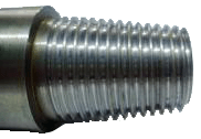
The die is used for cutting external threads on a pre-prepared workpiece, the diameter of which is determined by the diameter and pitch of the thread being cut.
The working (cutting) surface of the die has a conical intake part (chamfer) and a cylindrical calibrating part, which ensures cutting a thread of the required size. As a result of the presence of the intake part on the threaded rod, at the end of the thread there remains a section l 1 with a profile gradually decreasing in height (Figure 5.3, c). This section with incomplete threads is called thread run-out . A full profile thread, defined by the calibrating part of the die, ends on the rod where the thread starts to run out. In the case when the cut part of the rod is limited by some supporting surface (shoulder, head, shoulder, etc.), when cutting the thread (to avoid breakage) the die is usually not brought all the way to this surface.
In this case, a section called thread undercut. Escape plus undershoot form undercut thread l 2 (Figure 5.3, c).
 |
||
| A | b | V |
Figure 5.3 — Threading a rod
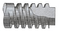
The tap (Figure 5.4) is used for cutting internal threads in a pre-drilled hole, the diameter d 1 of which is selected depending on the pitch and diameter of the thread being cut (see table 5.2. (GOST 19257-73. Holes for cutting metric threads)).
| Thread pitch, P | Drill diameter, d 1 | Nominal thread diameter, d | Thread pitch, P | Drill diameter, d 1 | |
|---|---|---|---|---|---|
| 1 | 0,2 | 0,80 | 10 | 0,5 | 9,50 |
| 0,25 | 0,75 | 0,75 | 9,25 | ||
| 1,1 | 0,2 | 0,90 | 1 | 9,00 | |
| 0,25 | 0,85 | 1,25 | 8,80 | ||
| 1,2 | 0,2 | 1,00 | 1,5 | 8,50 | |
| 0,25 | 0,95 | 11 | 0,5 | 10,50 | |
| 1,4 | 0,2 | 1,20 | 0,75 | 10,25 | |
| 0,3 | 1,10 | 1 | 10,00 | ||
| 1,6 | 0,2 | 1,40 | 1,25 | 9,50 | |
| 0,35 | 1,25 | 12 | 0,5 | 11,50 | |
| 1,8 | 0,2 | 1,60 | 0,75 | 11,25 | |
| 0,35 | 1,45 | 1 | 11,00 | ||
| 2 | 0,25 | 1,75 | 1,25 | 10,80 | |
| 0,4 | 1,60 | 1,5 | 10,50 | ||
| 2,2 | 0,25 | 1,95 | 1,75 | 10,20 | |
| 0,45 | 1,75 | 14 | 0,5 | 13,50 | |
| 2,5 | 0,35 | 2,15 | 0,75 | 13,25 | |
| 0,45 | 2,05 | 1 | 13,00 | ||
| 3 | 0,35 | 2,65 | 1,25 | 12,80 | |
| 0,5 | 2,50 | 1,5 | 12,50 | ||
| 3,5 | 0,35 | 3,15 | 2 | 12,00 | |
| 0,6 | 2,90 | 15 | 1 | 14,00 | |
| 4 | 0,5 | 3,50 | 1,5 | 13,50 | |
| 0,7 | 3,30 | 16 | 0,5 | 15,50 | |
| 4,5 | 0,5 | 4,00 | 0,75 | 15,25 | |
| 0,75 | 3,75 | 1 | 15,00 | ||
| 5 | 0,5 | 4,5 | 1,5 | 14,50 | |
| 0,8 | 4,20 | 2 | 14,00 | ||
| 5,5 | 0,5 | 5,00 | 17 | 1 | 16,00 |
| 6 | 0,5 | 5,50 | 1,5 | 15,50 | |
| 0,75 | 5,25 | 18 | 0,5 | 17,50 | |
| 1 | 5,00 | 0,75 | 17,25 | ||
| 7 | 0,5 | 6,50 | 1 | 17,00 | |
| 0,75 | 6,25 | 1,5 | 16,50 | ||
| 1 | 6,00 | 2 | 16,00 | ||
| 8 | 0,5 | 7,50 | 2,5 | 15,50 | |
| 0,75 | 7,25 | 20 | 0,5 | 19,50 | |
| 1 | 7,00 | 0,75 | 19,25 | ||
| 1,25 | 6,80 | 1 | 19,00 | ||
| 9 | 0,5 | 8,50 | 1,5 | 18,50 | |
| 0,75 | 8,25 | 2 | 18,00 | ||
| 1 | 8,00 | 2,5 | 17,50 | ||
| 1,25 | 7,80 |
 |
||
| A | b | V |
Figure 5.4 - Tapping a hole
Figure 5.4 shows a blind (non-through) hole. At its bottom there is a conical recess left from the drill. The angle at the apex of the cone is conventionally assumed to be equal to 120 0 , and its dimensions are not shown on the drawings.
Before cutting the thread at the end of the rod (for external threads) and at the beginning of the hole (for internal threads) chamfers , the conical surface of which forms an angle of 45 0 with the axis. The chamfer protects the outer turns from damage, simplifies the thread cutting process, and facilitates the connection of threaded parts with each other. The size of the chamfers is determined by the size of the thread pitch (Table 5.3).
The tap, like the die, has a conical intake part and a calibrating part. When cutting a thread with a tap, there will be a thread run-out, determined by the intake part of the tap, and a full profile thread. When cutting a thread in a blind hole, the tap (to avoid its breakage) is not brought all the way to the bottom of the hole, so there will be an undercut of the thread and, consequently, an undercut of the thread as the sum of the run-out and the undercut of the thread.
If you need to make a full profile thread, without a run, then to remove the thread-forming tool, make a groove, the diameter of which for external threads should be slightly less than the internal diameter of the thread (Figure 5.5, a), and for internal threads - slightly larger than the external diameter of the thread (Figure 5.5 , b).
The dimensions of chamfers, runs, undercuts, and grooves are standardized by GOST 10549-80* - Thread exit. Runs, undercuts, grooves and chamfers and GOST 27148-86 - Fasteners. Thread exit. Runaways, undercuts, grooves. Dimensions.
 |
|
| A | b |
Figure 5.5 — External and internal grooves
|
|||||||||||
| Thread pitch P | Groove | Chamfer z | |||||||||
|---|---|---|---|---|---|---|---|---|---|---|---|
| Type 1 | Type 2 | d f | when mating with internal thread with groove type 2 | for all other cases | |||||||
| normal | narrow | ||||||||||
| f | R | R 1 | f | R | R 1 | f | R 2 | ||||
| 0 ,2 | — | — | — | — | — | — | — | — | — | — | 0 ,2 |
| 0 ,25 | |||||||||||
| 0 ,3 | |||||||||||
| 0 ,35 | d — 0 ,6 | 0 ,3 | |||||||||
| 0 ,4 | 1 ,0 | 0 ,3 | 0 ,2 | ||||||||
| 0 ,45 | d — 0 ,7 | ||||||||||
| 0 ,5 | 1 ,6 | 0 ,5 | 0,3 | 1 ,0 | 0 ,3 | 0 ,2 | d — 0 ,8 | 0 ,5 | |||
| 0 ,6 | d — 0 ,9 | ||||||||||
| 0 ,7 | 2 ,0 | 1 ,6 | 0,5 | 0,3 | d — 1,0 | ||||||
| 0 ,75 | d — 1,2 | 1 ,0 | |||||||||
| 0 ,8 | 3,0 | 1 ,0 | 0 ,5 | ||||||||
| 1 | 2 ,0 | 3 ,6 | 2 ,0 | d — 1,5 | 2 ,0 | ||||||
| 1,25 | 4 ,0 | 2 ,5 | 1 ,0 | 0 ,5 | 4 ,4 | 2 ,5 | d — 1,8 | 2 ,5 | 1 ,6 | ||
| 1 ,5 | 4,6 | d — 2 ,2 | 3 ,0 | ||||||||
| 1,75 | 5 ,4 | 3 ,0 | d — 2 ,5 | 3 ,5 | |||||||
| 2 | 5 ,0 | 1 ,6 | 3,0 | 5 ,6 | d — 3 ,0 | 2 ,0 | |||||
| 2 ,5 | 6 ,0 | 1 ,0 | 4 ,0 | 7 ,3 | 4 ,0 | d — 3 ,5 | 5 ,0 | 2 ,5 | |||
| 3 | 7 ,6 | d — 4 ,5 | 6 ,5 | ||||||||
| 3 ,5 | 8 ,0 | 2 ,0 | 5 ,0 | 1 ,6 | 10 ,2 | 5 ,5 | d — 5 ,0 | 7,5 | |||
| 4 | 10,3 | d — 6 ,0 | 8,0 | 3,0 | |||||||
| 4 ,5 | 10 ,0 | 3 ,0 | 6 ,0 | 1 ,0 | 12 ,9 | 7 ,0 | d — 6 ,5 | 9 ,5 | |||
| 5 | 13 ,1 | d — 7 ,0 | 10 ,5 | 4 ,0 | |||||||
| 5 ,5 | 12 ,0 | 8 ,0 | 2 ,0 | 15,0 | 8 ,0 | d — 8 ,0 | |||||
| 6 | 16 ,0 | 8 ,5 | d — 9 ,0 | ||||||||
The rules for depicting and applying thread designations on drawings are established by GOST 2.311-68*.
The carving is depicted:
a) on the rod - with solid main lines along the outer diameter of the thread and solid thin lines - along the inner diameter for the entire length of the thread, including the chamfer. In the images obtained by projection onto a plane perpendicular to the axis of the rod, an arc is drawn along the internal diameter of the thread with a solid thin line, equal to 3/4 of the circle, open anywhere, but not along the axes (Figure 5.6, a);
b) in the hole - with solid main lines along the internal diameter of the thread and solid thin lines - along the outer diameter. In the images obtained by projection onto a plane perpendicular to the axis of the hole, an arc is drawn along the outer diameter of the thread with a solid thin line, equal to 3/4 of the circle, open anywhere (Figure 5.6b).
 |
|
| A | b |
Figure 5.6 - Representation of threads in the drawings: external - on the rod (a), internal - in the hole (b)
A solid thin line on the image of the thread is applied at a distance of at least 0.8 mm from the main line and no more than the thread pitch. The line defining the thread boundary is drawn on the rod and in the threaded hole at the end of the full thread profile (before the start of the run). The thread boundary is drawn to the line of the outer diameter of the thread and is depicted as a solid main or dashed line if the thread is depicted as invisible (Figure 5.7, 5.8), where l st- the length of the rod on which the thread is cut, l sv— the depth of drilling the hole for the thread.

Figure 5.7 - Image of the visible thread boundary

Figure 5.8 - Image of the invisible thread border
Hatching in sections and sections is carried out to the line of the outer diameter of the thread on the rods and to the line of the internal diameter in the hole, i.e. in both cases to the solid main line.
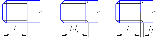
Thread length with full profile (without run-out) l) on the rod and in the hole are indicated as shown in Figure 5.7, 5.9.
If it is necessary to indicate the amount of run-off on the rod, the dimensions are applied as shown in Figure 5.9c. The thread run-out is depicted as a solid thin line drawn either along a radius or as a segment at approximately an angle of 30 0 (Figure 5.9b).
 |
||
| A | b | V |
Figure 5.9 - Image of thread run-out, thread length size
An undercut of a thread made all the way is shown as shown in Figure 5.7. Chamfers on a threaded rod and in a threaded hole that do not have a special structural purpose are not shown in projection onto a plane perpendicular to the axis of the rod or hole (Figure 5.6, a, b). A solid thin line of the thread on the rod should intersect the chamfer boundary line.
On sections of a threaded connection in the image on a plane parallel to its axis, only the part of the thread that is not covered by the thread of the rod is shown in the hole (Figure 5.10).

Figure 5.10 - Image of a threaded connection
Thread designations indicate, according to the relevant standards, the dimensions and maximum deviations of the thread and relate them to all threads, except conical and cylindrical pipe, to the outer diameter, as shown in Figures 5.4, 5.11.
 |
|
| A | b |
Figure 5.11 — Applying dimensions to threads
The designation of tapered threads and cylindrical pipe threads is applied as shown in Figure 5.12.

Figure 5.12 — Dimensions on pipe and tapered threads
Metric threads are most widely used in engineering.
The thread profile (Figure 5.2) is established in GOST 9150-81; the main dimensions (nominal values) of the outer, middle and inner thread diameters are in GOST 24705-2004; diameters and pitches - GOST 8724-81 (Appendix A) - see table 5.6.
M.Metric threads are made with large(the only one for a given thread diameter) and small in steps, which can be several for a given diameter. Therefore, in the designation of metric threads, the large pitch is not indicated, but the small pitch is required.
Designation: M20x1.5-6g - metric external thread (on the rod) with a diameter of 20 mm with a fine pitch of 1.5 mm (Fig. 5.11, a); M20 LH-6g – the same left, with a large pitch; M20x1.5 LH-6g – the same with fine pitch; M20-6N – internal thread (in the hole) with a large pitch (Fig. 5.11, b). Specifying the thread tolerance range is mandatory.
Metric tapered thread (GOST 25229-82) is used to connect pipelines.
Designation: MK8*1 - metric conical with a diameter of 8 mm, measured in the main plane and in increments of 1 mm (Fig. 5.12, b).
Cylindrical pipe threads in accordance with GOST 6357-81 are used on water and gas pipes, parts for their connection (couplings, elbows, crosses, etc.), pipeline fittings (gate valves, etc.).
The profile of a cylindrical pipe thread is shown in Figure 5.2.
The symbol includes the letter G, thread size in inches, accuracy class of the average thread diameter - A or B (less accurate) and screwing length in mm, if it exceeds the normal one established by the standard.
Example: G 1/2 (Fig. 5.12, a), G 1/4-A, G 1/2 LH-A, G 3/8-A-20.
If for a metric thread the diameter size indicated in the designation corresponds to its actual size (without taking into account tolerance), then in a pipe thread the size in inches indicated in the designation is approximately equal to nominal diameter of the pipe(nominal internal diameter by which its throughput is calculated), converted to inches.
For example, G1 denotes the size of a pipe thread cut on the outer surface of a pipe having a nominal bore of 25 mm, i.e. approximately 1 inch. In fact, the outer diameter of the pipe is 33.249 mm, i.e. more than two pipe wall thicknesses - table 5.5.
Therefore, the designation of the pipe thread size is applied on the shelf of the leader line (Figure 5.13).

Figure 5.13 — Pipe thread designation
| Thread size inch | 1/4 | 3/8 | 1/2 | 3/4 | 1 | 1 ¼ |
|---|---|---|---|---|---|---|
| Conditional pass , mm | 9 | 10 | 15 | 20 | 25 | 40 |
| Pipe outer diameter, mm | 13,5 | 17,0 | 21,3 | 26,8 | 33,5 | 48,0 |
| Outer thread diameter, mm | 13,16 | 16,67 | 20,96 | 26,44 | 33,25 | 47,80 |
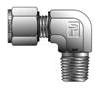
Tapered pipe threads in accordance with GOST 6211-81 are used in pipe connections at high pressures and temperatures, when increased tightness of the connection is required.
For thread profile, see Figure 5.2. Since the diameter of the tapered thread is constantly changing, its size is referred to the section in the main plane (approximately in the middle of the length of the external thread). In this section, the diameter of the tapered thread is equal to the diameter of the cylindrical pipe thread (Figure 5.14). The position of the main plane is indicated on the working drawing (taken from the standard).

Figure 5.14 — Designation of pipe tapered thread
External thread is designated by the letter R, internal – Rc.
The designation of a tapered pipe thread includes the letter R(Rc) and the size in inches without specifying the dimension.
Example: R 1 1/2 LH - outer left, Rс 1/8 - inner (Fig. 5.12, c).
Conical inch threads (GOST 6111-52) are used in connections of fuel, oil, water, air pipelines of machines and machine tools at low pressures.
The designation consists of the letter TO and thread size in inches, indicating the dimension, is applied on the shelf of a leader line, as with pipe threads.
Example: To 3/4″ GOST 6111-52.
Round threads are used for mixer valve spindles in accordance with GOST 19681-94 (Sanitary water fittings) and water taps in accordance with GOST 20275-74.
The designation for round threads includes the letters Kr, nominal thread diameter in mm, thread pitch in mm and GOST 13536-68.
Example: Kr 12x2.54 GOST 13536-68, where 2.54 is the thread pitch in mm, 12 is the nominal thread diameter in mm. GOST 13536-68 defines the profile, main dimensions and tolerances of round threads.
Used on screws that transmit reciprocating motion and axial force. Carving happens single-pass And multi-pass .
The thread profile is shown in Figure 5.2.
The main dimensions, diameters, pitches, tolerances of single-start threads are standardized according to GOST 24737-81, 24738-81, 9562-81.
For multi-start threads, these parameters are found in GOST 24739-81 *.
Symbol for single-start thread consists of letters Tr, values of the nominal thread diameter, pitch, tolerance range.
Example: Tr 40x6-8e - trapezoidal single-start external thread with a diameter of 40 mm with a pitch of 6 mm, Tr 40x6-8e-85 - the same make-up length 85 mm, Tr 40x6LH-7N - the same for the internal left.
IN symbol for multi-start thread the numerical value of the stroke is added: Tr 20x8(P4)-8e – trapezoidal multi-start external thread with a diameter of 20 mm with a stroke of 8 mm and a pitch of 4 mm.
It is used on screws subject to unilaterally directed forces, for example in jacks.
Alena Grishchuk Traditions and culture of the Christian family, in moral education...


Each radix planet is considered to move at a rate of one degree per year, and...