Quite often, the population is interested in how to find out if an apartment has been privatized or ...


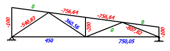
Determination of the internal forces of the truss
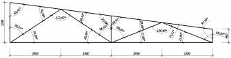


Ra+Rb-100-200-200-200-100=0;
200*1.5 +200*3+200*4.5+100*6-Rb*6=0;
Rb=(200*1.5 +200*3+200*4.5+100*6) / 6;
Rb=400 kg
Ra=100+200+200+200+100-Rb;
Ra=800-400=400 kg;
If it turned out that the forces in the rod are directed from the center, then our rod tends to stretch (return to its original position), which means that it is compressed. And if the efforts of the rod are directed towards the center, then the rod tends to shrink, that is, it is stretched.
So, let's move on to the calculation. There are only 2 unknown quantities in node 1, so let's consider this node (we set the directions of efforts S1 and S2 from our own considerations, in any case, we will get it right in the end).
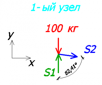
S2 * sin82.41 = 0; - on the x-axis
-100 + S1 = 0; - on the y-axis
Since the value of S1 turned out to be positive, it means that we have chosen the direction of effort correctly! If it would turn out to be negative, then the direction should be changed and the sign should be changed to “+”.

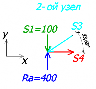
100 + 400 - sin33.69 * S3 = 0 - on the y-axis
- S3 * cos33.69 + S4 = 0 - on the x-axis

100 + S13 = 0 - on the y-axis
-S11 * cos7.59 = 0 - on the x-axis
S13 = 100 kg (rod #13 compressed)
S11 = 0 (zero rod, there is no effort in it)
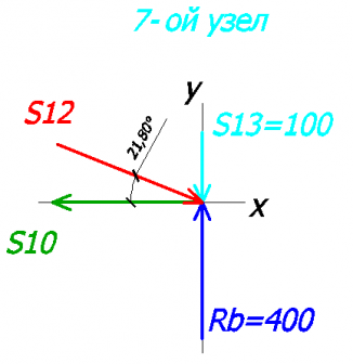
100 + 400 - S12 * sin21.8 = 0 - on the y-axis
S12 * cos21.8 - S10 = 0 - on the x-axis
S12 = 807.82 kg (rod #12 compressed)
S10 = 750.05 kg (rod #10 stretched)

200 + 540.83 * sin33.69 - S5 * cos56.31 + S6 * sin7.59 = 0 - to the y-axis
540.83 * cos33.69 - S6 * cos7.59 + S5 * sin56.31 = 0 - on the x-axis
S5 = 360.56 kg (rod #5 stretched)
S6 = 756.64 kg (rod #6 compressed)

200 - S8 * sin7.59 + S9 * sin21.8 + 807.82 * sin21.8 = 0 - on the y-axis
S8 * cos7.59 + S9 * cos21.8 - 807.82 * cos21.8 = 0 - on the x-axis
S8 = 756.64 kg (rod #8 compressed)
S9 = 0 kg (rod #9 zero)

200 + S7 - 756.64 * sin7.59 + 756.64 * sin7.59 = 0 - on the y-axis
756.64 * cos7.59 - 756.64 * cos7.59 = 0 - on the x-axis
S7 = 200 kg (rod #7 compressed)
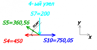
200 + 360.56 * sin33.69 = 0 - on the y-axis
-360.56 * cos33.69 - 450 + 750.05 = 0 - on the x-axis
In the 2nd equation:
This error is acceptable and is most likely due to the angles (2 decimal places instead of 3).
As a result, we get the following values:

Selection of the section of the truss elements
Ministry of Science and Education of the Russian Federation Federal Agency for Education State educational institution
higher professional education "Rostov State Construction University"
CALCULATION OF FLAT FARMS
Methodical instructions and control tasks for students of the correspondence department
Rostov-on-Don
Calculation of flat farms: Methodological instructions and control tasks for students of the correspondence department. - Rostov-on-Don: Rost. state builds. un-t, 2006 - 23 p.
Designed for students of the correspondence department of all specialties. Various methods for calculating flat trusses are given and solutions to typical examples are analyzed.
Compiled by: T.V. Vilenskaya S.S. Savchenkova
Reviewer: npof. I.F. Khrjiyants
Editor N.E. Gladkikh Templan 2006, pos. 171
Signed for publication on May 24, 2006. Format 60x84/16. Writing paper. Risograph. Uch.-ed. l.. 1.4. Circulation 100 copies. Order Editorial and publishing center RSSU
344022, Rostov n / a, st. Socialist, 162
© Rostov State University of Civil Engineering, 2006
INTRODUCTION
In the construction of bridges, cranes and other structures, structures called trusses are used.
A farm is a structure consisting of rods connected to each other at the ends by hinges and forming a geometrically unchanging system.
The hinged joints of the truss rods are called its nodes. If the axes of all the truss rods lie in the same plane, then the truss is called flat.
We will consider only flat trusses. We assume that the following conditions are met:
1) all truss rods are straight;
2) there is no friction in the hinges;
3) all specified forces are applied only in the truss nodes;
4) the weight of the rods can be neglected.
In this case, each truss rod is under the action of only two forces that will cause it to stretch or compress.
Let the truss have "m" rods and "n" nodes. Let's find the relationship between m and n, which ensures the rigidity of the structure (Fig. 1).
To connect the first three nodes, three rods are needed, for the rigid connection of each of the remaining (n-3) nodes, 2 rods are needed, that is
or m = 2n-3. (one)
If m< 2n - 3, то конструкция не будет геометрически неизменяемой, если m >2n - 3, the truss will have an "extra" rod.
Equality (1) is called the rigidity condition.
The farm shown in Fig. 1 is a rigid structure
Rice. 1 The calculation of the farm is reduced to the determination of support reactions and forces in
rods, that is, the forces acting from the nodes on the rods adjacent to it.
Let us find out at what ratio between the number of rods and nodes the truss will be statically determinate. If all unknown forces can be determined from the equilibrium equations, that is, the number of independent equations is equal to the number of unknowns, then the construction is statically determinate.
Since a flat system of converging forces acts on each truss node, it is always possible to compose 2n equilibrium equations. The total number of unknowns is m + 3, (where m is the effort in the rods and 3 are the support reactions).
The condition of static definability of the truss m + 3 = 2n
or m = 2n - 3 (2)
Comparing (2) with (1), we see that the condition of static definability coincides with the rigidity condition. Therefore, a rigid truss without extra rods is statically determinate.
DETERMINATION OF SUPPORT REACTIONS
To determine the support reactions, we consider the equilibrium of the entire truss as a whole under the action of an arbitrary planar system of forces. We compose three equilibrium equations. After finding the support reactions, it is necessary to make a check.
DETERMINATION OF FORCES IN THE RODS OF THE TRUSS Forces in the stubble of the farm can be determined in two ways:
cutting out nodes and the section method (Ritter method).
The method for cutting nodes is as follows:
the equilibrium of all nodes of the truss, which are under the action of external forces and reactions of cut rods, is considered sequentially. A flat system of converging forces is applied to each node, for which two equilibrium equations can be drawn up. It is advisable to start the calculation from the node where two rods converge. In this case, one equilibrium equation of the penultimate node and two equations of the last node are test ones.
The Ritter method is as follows:
the truss, to which external forces are applied, including the reactions of the supports, is cut into two parts along three rods, if possible. The number of bars cut should include the forces that you want to determine.
One of the parts of the farm is discarded. The effect of the discarded part on the remaining part is replaced by unknown reactions.
The equilibrium of the remaining part is considered. Equilibrium equations are compiled so that each of them includes only one unknown. This is achieved by a special choice of equations: when compiling the equation of moments, the moment point is chosen where the lines of action of two unknown forces intersect, which are not currently determined. When compiling the projection equation, the projection axis is chosen perpendicularly

two parallel efforts.
When compiling equilibrium equations by both methods, it is assumed that all rods are stretched. If the result is negative, the rod is compressed.
Typical example: Determine the support reactions and forces in the truss rods, if F=20 kH, P=20 kH, α=60°, Q=30 kN. (Fig. 2, 3).
We determine the support reactions, considering the equilibrium of the system as a whole (Fig. 3).
∑ X \u003d 0: X A -F cos α + Q \u003d 0;
∑ H \u003d 0: Y A + YB - P - F sin α \u003d 0;
∑ M A \u003d 0: -Q a - P 2a - F sin α 3a + F cos α a + YB 4a \u003d 0.
Solving these equations, we find:
XA = -20 kH; YА = 9.33 kH; YB = 28 kH.
Let's check the correctness of the obtained results. To do this, we compose the sum of the moments of forces about the point C.
∑ MS \u003d XA a - YA a - P a - F sin α 2a + YB 3a \u003d \u003d (-20 - 9.33 - 20 - 20 1.73 + 28 3) a \u003d 0.
Let's move on to determining the forces in the truss rods.
Knot cutting method.
We start the calculation from node A, where two rods converge.
You should depict the node whose equilibrium is being considered (Fig. 4). Since we assume that all rods are stretched, we direct the reactions of the rods away from the node (S 1 and S 5 ). Then the forces in the rods (reactions
For node A, we compose two equilibrium equations:
∑ X \u003d 0: + X A + S5 + S1 cos 45 ° \u003d 0;
∑ Y \u003d 0: Y A + S1 cos 45 ° \u003d 0.
We get: S 1 13.2 kH;
S 5 29.32kH .
∑ X \u003d 0: Q + S 2 + S6 cos 45 ° - S1 cos 45 ° \u003d 0;
∑ Y = 0:- S 1 cos 45° - S6 cos 45° = 0.
When substituting the value of S1, we take into account that the force is negative.
We get: S 6 13.2 kH;
S2 48.7kH .
Other nodes are calculated similarly (Fig. 6.7).
∑ X \u003d 0: - S 2 - S7 cos 45 ° - S3 cos 45 ° - F cos α \u003d 0;
∑ Y = 0:- S 7 cos 45° - S3 cos 45° - F sin α = 0.
Hence: S 3 39.6 kH ;
S 7 15.13kH .
∑ X \u003d 0: - S 4 - S3 cos 45 ° \u003d 0;
Second test equation:
∑ Y = +Y B + S3 cos 45° = 28-39.6 0.71 =0. S4 = 28.0kH.
To check, consider the equilibrium of node E. (Fig. 8)
∑ X \u003d - S 5 + S4 - S6 cos 45 ° + S7 cos 45 ° \u003d 0;
∑ Y = S 6 cos 45° + S7 cos 45° - P = 0.
Since the equations turned into identities, the calculation was made correctly.
Section method (Ritter method).
The Ritter method is convenient to use if it is required to determine the forces not in all the rods, and as a test method, since it allows you to determine each effort independently of the others.
We determine the forces in the rods 2, 6, 5. We cut the truss into two parts along the rods 2, 6, 5. We discard the right side and consider the balance of the left
To determine the force S5, we draw up an equation of moments about the point where the forces S2 and S6 intersect (point C).
∑ MS = 0: ХА a – YA a + S5 a = 0;. S5 = 29.32 kH.
To determine the force S2, we draw up an equation of moments about point E:
∑ ME \u003d 0: - Q a - S2 a - YA 2a \u003d 0; S2 = 48.64kH.
To determine the force S6, an equation of projections on the Y-axis should be drawn up:
∑ Y = 0:-S6 cos 45° + YA = 0; S6 = 13.2kH.
The results should be entered in table. one.
Forces in truss rods, kN
rod number, method |
||||||||
cutting out |
||||||||
Ritter's method |
||||||||
FARM CALCULATION USING THE POSSIBLE MOVEMENT PRINCIPLE
The principle of possible displacements is the basic principle of analytical mechanics. It gives the most general methods for solving problems of statics and allows you to determine each unknown force independently of all the others, making up for it one equilibrium equation.
The principle of possible displacements (theorem of Lagrange-Ostrogradsky):
For the equilibrium of a mechanical system subject to ideal, geometric and stationary constraints, it is necessary and sufficient that the sum of the work of the active forces acting on the system be equal to zero on any possible displacement of the system:
A k ( a ) 0 . k 1
Fixed communications- connections that are explicitly independent of time.
Ideal bonds are bonds, the sum of the work of reactions of which on any possible displacement of the system is equal to zero.
Geometric links- links that impose restrictions only on the coordinates of the points of the system.
Active forces - forces acting on the system, except for the coupling reactions.
Possible system movements
Possible displacements of a mechanical system are infinitesimal displacements of the system allowed by the constraints imposed on it.
The values of possible displacements are indicated by symbols, for example - δ S, δφ, δX.
Let us give examples of possible displacements of systems (we restrict ourselves to the consideration of flat systems):
1. The body is fixed by a fixed hinge, allowing the body to rotate around an axis passing through the point O, perpendicular to

drawing plane (Fig. 10).
Possible movement of the body - rotation around the axis at an angle δφ.
2. The body is fixed with two movable hinges
These connections allow the body to move translationally parallel to the planes of the rollers.
Possible movement of the body - δX.
3. The body is also fixed with two movable hinges (the planes of the rollers are not parallel).
These links allow the flat body to move only in the drawing plane. The possible displacement of this body will be a plane-parallel displacement. And the plane-parallel movement of the body can at the moment be considered as a rotational movement around an axis passing through
instantaneous center of body velocities (m.c.s.) perpendicular to the plane of the drawing
Therefore, in order to see the possible movement of a given body, one must know where the m.c.s. this body. To build an MCS, you need to know the directions of the velocities of two points of the body, draw perpendiculars to the velocities at these points, the point of intersection of the perpendiculars will be the MCS. body. In the example, we know the directions of the velocities of points A and B (they are parallel to the planes of the rollers). This means that the possible displacement of this body is a rotation through an angle δφ around an axis passing through point A perpendicular to the plane of the drawing.
CONCLUSION: Since only flat systems are considered below, in order to see the possible displacement of a system consisting of flat solid bodies, it is necessary to see or build for each solid body

there will be a turn around its m.c.s., or the body will move forward if the m.c.s. missing. The possible displacements of the system are determined only by the constraints imposed on the system and do not depend on the forces acting on the system. In the case of geometric and stationary connections, the directions of possible displacements of the points of the system coincide with the directions of the velocities of these points during real movement.
The work of a force on a possible displacement
In the problems under consideration, solid bodies will be able to either move translationally or rotate around an axis perpendicular to the plane of the drawing. Let's write the formulas for finding the possible work of the force during such displacements of bodies.
1. The body moves forward.
Then each point of the body is moved by r . Therefore, the point of application of the force F moves to r. Then A F r .
Special cases:
A0.
2. The body rotates around an axis.
The work of the force F is found as the elementary work of the force applied to the rotating body. The body rotates through an angle δφ.
δA \u003d Mz (F) δφ,
where Mz (F) is the moment of force F relative to the axis of rotation of the body (in our problems, the z axis is perpendicular to the plane of the drawing and finding Mz (F) is reduced to finding the moment of force F relative to the point of intersection of the axis with the plane).
δA > 0, if the force creates a moment directed in the direction of rotation of the body;.
δA< 0 , если сила создаёт момент, направленный в сторону, противоположную вращению тела.
The study of these issues is necessary in the future to study the dynamics of the movement of bodies, taking into account sliding friction and rolling friction, the dynamics of the center of mass of a mechanical system, kinetic moments, to solve problems in the discipline "Strength of materials".
Farm called a rigid structure of straight rods connected at the ends by hinges. If all the bars of a truss lie in the same plane, the truss is said to be flat. The junctions of the truss rods are called nodes. All external loads to the farm are applied only at the nodes. When calculating the truss, the friction in the nodes and the weight of the rods (compared to external loads) are neglected or the weights of the rods are distributed over the nodes.
Then, each of the truss rods will be acted upon by two forces applied to its ends, which, in equilibrium, can only be directed along the rod. Therefore, we can assume that the truss rods work only in tension or compression. We restrict ourselves to consideration of rigid flat trusses, without extra rods formed from triangles. In such trusses, the number of rods k and the number of nodes n are related by the relation
The calculation of the farm is reduced to the determination of support reactions and forces in its rods.
Support forces can be found by conventional static methods, considering the truss as a whole as a rigid body. Let's move on to determining the forces in the rods.
Knot cutting method. This method is convenient to use when you need to find the effort in all the rods of the farm. It comes down to a sequential consideration of the conditions for the balance of forces converging in each of the truss nodes. Let us explain the course of calculations with a specific example.
Fig.23
Consider the one shown in Fig. 23, and a farm formed from identical isosceles right triangles; forces acting on the farm are parallel to the axis X and are equal: F 1 \u003d F 2 \u003d F 3 \u003d F \u003d 2.
Nodes in this farm n= 6, and the number of rods k= 9. Therefore, the relation is satisfied and the truss is rigid, without extra rods.
Compiling the equilibrium equations for the farm as a whole, we find that the reactions of the supports are directed, as shown in the figure, and are numerically equal;
Y A = N = 3/2F = 3H
Let's move on to determining the forces in the rods.
We number the truss nodes in Roman numerals, and the rods in Arabic. The desired effort will be denoted S 1 (in rod 1), S 2 (in rod 2), etc. Let's mentally cut off all the nodes together with the rods converging in them from the rest of the farm. The action of the discarded parts of the rods will be replaced by forces that will be directed along the corresponding rods and are numerically equal to the desired efforts S 1 , S 2.
We depict all these forces at once in the figure, directing them from the nodes, i.e., considering all the rods to be stretched (Fig. 23, a; the depicted picture must be imagined for each node as shown in Fig. 23, b for node III). If, as a result of the calculation, the value of the force in any rod turns out to be negative, this will mean that this rod is not stretched, but compressed. Letter designations for forces acting along the rods, neither fig. 23 not inputs, since it is clear that the forces acting along the rod 1 are numerically equal S 1 , along rod 2 are equal S 2 etc.
Now, for the forces converging at each node, we sequentially compose the equilibrium equations:
We start from node 1, where two rods converge, since only two unknown forces can be determined from the two equilibrium equations.
Compiling the equilibrium equations for node 1, we obtain
F 1 + S 2 cos45 0 = 0, N + S 1 + S 2 sin45 0 = 0.
From here we find:
Now knowing S 1 , go to node II. For him, the equilibrium equations give:
S 3 + F 2 \u003d 0, S 4 - S 1 \u003d 0,
S 3 \u003d -F \u003d -2H, S 4 \u003d S 1 \u003d -1H.
Having defined S 4 , we compose the equilibrium equations in a similar way, first for node III, and then for node IV. From these equations we find:
Finally, to calculate S 9 we compose an equation for the balance of forces converging at the node V, projecting them onto the By axis. We get Y A + S 9 cos45 0 = 0 from where
The second equilibrium equation for node V and two equations for node VI can be compiled as verification. To find the forces in the rods, these equations were not needed, since instead of them, three equilibrium equations for the entire truss as a whole were used in determining N, X A, and Y A.
The final results of the calculation can be summarized in the table:
As the force signs show, rod 5 is stretched, the rest of the rods are compressed; rod 7 is not loaded (zero, rod).
The presence of zero rods in the truss, similar to rod 7, is detected immediately, since if three rods converge in a node not loaded by external forces, two of which are directed along one straight line, then the force in the third rod is zero. This result is obtained from the equation of equilibrium in projection onto the axis perpendicular to the mentioned two rods.
If during the calculation a node is encountered for which the number of unknowns is more than two, then the method of sections can be used.
Section method (Ritter method). This method is convenient to use to determine the forces in individual truss rods, in particular, for verification calculations. The idea of the method is that the truss is divided into two parts by a section passing through three rods, in which (or in one of which) it is required to determine the force, and the balance of one of these parts is considered. The action of the discarded part is replaced by the corresponding forces, directing them along the cut rods from the nodes, i.e., considering the rods to be stretched (as in the method of cutting nodes). Then they make up the equilibrium equations, taking the centers of moments (or the axis of projections) so that only one unknown force enters into each equation.
Graphical calculation of flat farms.
The calculation of the farm by the method of cutting out nodes can be done graphically. To do this, first, determine the support reactions. Then, successively cutting off each of its nodes from the farm, they find the forces in the rods converging at these nodes, building the corresponding closed force polygons. All constructions are carried out on a scale that must be pre-selected. Calculations start from the node in which two rods converge (otherwise it will not be possible to determine the unknown forces).
Fig.24
As an example, consider the farm depicted in fig. 24, a. Nodes in this farm n= 6, and the number of rods k= 9. Consequently, the relation is satisfied and the truss is rigid, without extra rods. The support reactions and for the considered farm are depicted along with the forces and as known.
We begin the determination of the forces in the rods by considering the rods converging at node I (we number the nodes in Roman numerals, and the rods in Arabic). Having mentally cut off the rest of the truss from these rods, we discard its action of the discarded part and also mentally replace it with forces and , which should be directed along rods 1 and 2. From the forces converging at node I , and build a closed triangle (Fig. 24, b).
To do this, we first depict a known force on a selected scale, and then draw straight lines through its beginning and end parallel to rods 1 and 2. In this way, forces and acting on rods 1 and 2 will be found. Then we consider the equilibrium of the rods converging at the node II. The action on these rods of the discarded part of the farm is mentally replaced by the forces , , and , directed along the corresponding rods; while the force is known to us, since by the equality of action and reaction.
Having built a closed triangle from the forces converging at node II (starting with force), we find the values S 3 and S 4 (in this case S 4 = 0). Similarly, the forces in the remaining rods are found. The corresponding force polygons for all nodes are shown in fig. 24b. The last polygon (for node VI) is built for verification, since all the forces included in it have already been found.
From the constructed polygons, knowing the scale, we find the magnitude of all efforts. The sign of the force in each rod is determined as follows. Having mentally cut the node along the rods converging in it (for example, node III), we apply the found forces to the cutoffs of the rods (Fig. 25); the force directed from the node ( in Fig. 25) stretches the rod, and the force directed towards the node ( and in Fig. 25) compresses it.
Fig.25
According to the accepted condition, we assign the sign “+” to the tensile forces, and the sign “-” to the compressive ones. In the considered example (Fig. 25), rods 1, 2, 3, 6, 7, 9 are compressed, and rods 5, 8 are stretched.
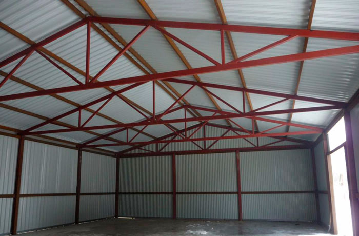
Metal trusses from a profile pipe are metal structures, the assembly of which is carried out by means of lattice metal rods. Their manufacture is a rather complicated and time-consuming process, but the result usually justifies expectations. An important advantage can be called the cost-effectiveness of the resulting design. In the production process, paired metal and scarves are often used as connecting metal parts. The further assembly process is based on riveting or welding.
A metal truss has many advantages. With their help, you can easily block the span of any length. However, it should be understood that the correct installation involves the primary competent calculation of the farm from the profile pipe. In this case, it will be possible to be sure of the quality of the created metal structure. It is also worth sticking to the planned plans, drawing and markings so that the product turns out in accordance with the requirements.
The benefits of this product do not end there. The following advantages can also be distinguished:
A truss from a profile pipe has characteristic features that should be remembered in advance. Based on the division, certain parameters can be distinguished. The main value is the number of belts. The following types can be distinguished:

The second important parameter, without which a farm drawing cannot be created, is the contours and shape. Depending on the latter, straight, gable or single-slope, arched trusses can be distinguished. Along the contour, metal structures can also be divided into several options. The first is designs with a parallel belt. They are considered the best solution for creating a soft roof. The metal support is extremely simple, and its components are identical, the grid is the same size as the rods, making installation an easy job.
The second option is single-pitched metal structures. They are based on rigid knots that provide resistance to external loads. The creation of such a design is distinguished by the economy of the material and, accordingly, low costs. The third type is polygonal farms. They are distinguished by a long and rather complicated installation, and the ability to withstand a lot of weight becomes an advantage. The fourth option is triangular trusses from a profile pipe. They are used if it is planned to create a metal truss with a large angle of inclination, but the disadvantage will be the presence of waste after construction. 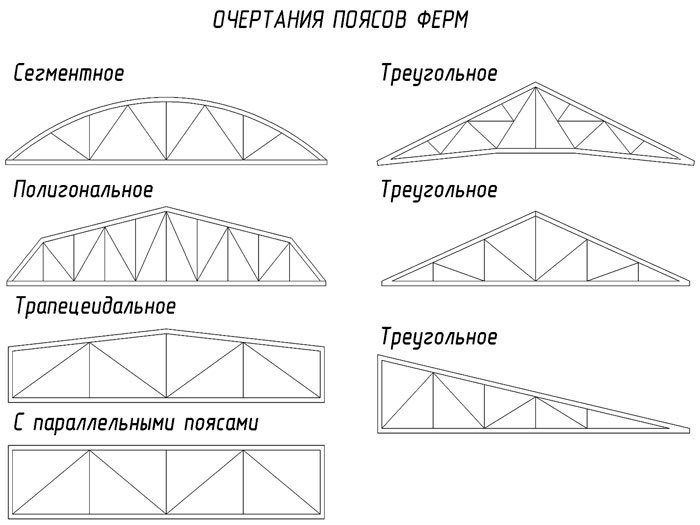
The next important parameter is the angle of inclination. Depending on it, metal trusses from profile pipes are divided into three main groups. The first group includes metal structures with an angle of inclination of 22-30 degrees. In this case, the length and height of the product are represented by a ratio of 1:5. Among the advantages of such a metal structure, one can single out a slight weight. Most often, metal triangular trusses are created this way.
In this case, it may be necessary to use braces mounted from top to bottom if the span height exceeds 14 meters. A panel 150-250 cm long will be located in the upper belt. As a result, a design with two belts and an even number of panels will be obtained. Provided that the span is more than 20 meters, the under-rafter metal structure should be mounted, linking it with support columns.
The second group includes farms from square pipes or from professional pipes and other varieties, if the angle of inclination is 15-22 degrees. The ratio of height and length between themselves reaches 1:7. The maximum frame length should not exceed 20 meters. If it is necessary to increase the height, additional procedures are required, for example, a broken belt is created.
The third group includes metal structures with an inclination angle of less than 15 degrees. In these projects, a trapezoid truss system is used. They have additional short racks. This allows you to increase the resistance to longitudinal deflection. If a shed roof is mounted, the angle of inclination of which reaches 6-10 degrees, it is necessary to consider an asymmetric shape. The division of the span may vary depending on the design features, and can be up to seven, eight or nine parts.
Separately, the Polonso farm, mounted by hand, is singled out. It is represented by two triangular trusses, which are connected by a puff. This eliminates the installation of long braces, which would have to be located in the middle panels. As a result, the weight of the structure will be optimal. 
The calculation and manufacture of trusses from a profile pipe should be based on the basic requirements that are prescribed in SNiP. When calculating, it is important to draw up a drawing of the product, without which subsequent installation will be impossible. Initially, a diagram should be prepared, which will indicate the main dependencies between the roof slope and the length of the structure as a whole. In particular, the following should be taken into account:
It should be remembered that increasing the height with your own hands will lead to an increase in bearing capacity. In this case, the snow cover will not be held on the roof. To further strengthen the metal structure, you will have to mount stiffeners. To determine the dimensions of the farm, you should be guided by the following data:
Next, you need to calculate the step, for this, the distance from one to the next support of the canopy is taken into account. Often it is standard and reaches 1.7 meters. If you break this unspoken rule, the strength of the structure may be somewhat violated. After all the required parameters are calculated, it is necessary to obtain a design diagram. To do this, use the program to achieve the required strength. Most programs have similar names to the process they are running. You can choose the program "Truss Calculation", "Truss Calculation 1.0" and other similar ones. 
When calculating, be sure to take into account the cost of one ton of metal in the purchase, as well as the cost of manufacturing the metal structure itself, that is, the costs of welding, anti-corrosion treatment and installation. Now it remains to figure out how to weld a truss from a profile pipe.
In order for truss welding to be of high quality, a number of recommendations must be followed. Among them are the following:

In order for the design to turn out in accordance with the requirements, it is important to adhere to a certain algorithm of work. Initially, the site is marked. To do this, mount vertical supports and embedded parts. If necessary, metal profile pipes can be immediately placed in pits and concreted. The installation of vertical supports is verified with a plumb line, and in order to control the parallelism, they pull the cord.
Enter dimensions in millimeters:
X– The length of the triangular truss truss depends on the size of the span to be covered and how it is attached to the walls. Wooden triangular trusses are used for spans 6000-12000 mm long. When choosing a value X it is necessary to take into account the recommendations of SP 64.13330.2011 "Wooden structures" (updated edition of SNiP II-25-80).
Y– The height of the triangular truss is given by the ratio 1/5-1/6 of the length X.

Z– thickness, W- The width of the timber for the manufacture of the farm. The desired section of the beam depends on: loads (permanent - the own weight of the structure and the roofing pie, as well as temporarily acting - snow, wind), the quality of the material used, the length of the overlapped span. Detailed recommendations on choosing a beam section for the manufacture of a truss are given in SP 64.13330.2011 "Wooden structures", SP 20.13330.2011 "Loads and impacts" should also be taken into account. Wood for load-bearing elements of wooden structures must meet the requirements of grades 1, 2 and 3 according to GOST 8486-86 “Softwood lumber. Specifications".
S– Number of uprights (internal vertical beams). The more racks, the higher the material consumption, weight and bearing capacity of the truss.
If you need struts for the truss (relevant for long trusses) and numbering of parts, mark the appropriate items.
By checking the “Black and white drawing” item, you will receive a drawing that is close to the requirements of GOST and will be able to print it without wasting color ink or toner.
Triangular wooden trusses are mainly used for roofs made of materials requiring a significant slope. An online calculator for calculating a wooden triangular truss will help determine the required amount of material, make truss drawings with dimensions and part numbering to simplify the assembly process. Also, using this calculator, you can find out the total length and volume of lumber for a truss truss.
Quite often, the population is interested in how to find out if an apartment has been privatized or ...

In all organizations, as a rule, sooner or later there is a change ...

A lot of people are thinking about how to find out whether an apartment has been privatized or not...